Section
9.
Theory of Operation Toyota Orderpicker Model
7BPUE
15
Service Manual
Steering
Steering
The Steering Encoder is located on the
operator's carriage, behind the steering wheel.
When the battery is connected, the key switch
is ON and the
deadman pedal is down, the
following events occur when the operator turns
the steering wheel in either direction:
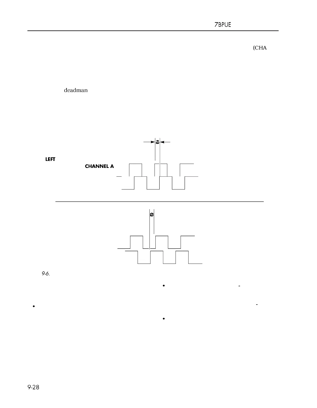
The steering encoder sends a quadrature
-
phase
output to the CM when the steering wheel is
turned. As the steering wheel is turned, two
individual square waves are produced
(CHA and
CHB). The relationship between these two
square waves tells the CM which way the
steering wheel is turning. The number of pulses
generated tells it of how far and how fast the
steering wheel has been turned. The degree of
rotation of the drive unit is not in direct
correlation to the distance the steering wheel is
turned. Once the steering wheel stops turning,
the drive unit stops turning. Determining which
way the steering wheel is turned is based on
which one of the two square waves is ahead of
the other. The one that is ahead tells which way
the wheel is turning. See Figure
9
-
6.
CHANNEL A leads
CHANNEL
B
by
LEFC
TURN
angle
0
CHANNEL
B
nnl
RIGHT TURN
CHANNEL A
CHANNEL
B
Figure
9-6.
Steer Position Encoder Output
CHANNEL A lags
CHANNEL
B
by
angle
0
These square waves are read by the CM. The
CM sends this information over the transmit
line to the STM.
The STM sends voltages to the steer power
head to activate the steer motor. STEER
DIR
1
and STEER DIR
1
PWM turn on the
transistors required to turn in one
direction. The STEER DIR
2
inputs will
turn it the other direction.
The BOOST
+
and BOOST
-
inputs are
required for both steering directions.
BOOST
+
is used to power on set of
transistors for steering and Boost
-
is used
for the reference by Boost
+.
While the steering is activated the Steer
Power Head sends a voltage to the STM
that indicates the current draw of the
motor over the STEER CURRENT FB.
There is also a voltage that is sent over the
STEER CURRENT LIMIT whenever the
motor is in current limit.
00700
-
C L2 2 2
-
05,
1
5
March
2
005
 Loading...