Subject: Deadman Pedal Switch Replacement Page 2 of 4
INSTALLATION PROCEDURE A
Switch Replacement for “Bolt-on” Type Deadman Pedal
1. Raise the carriage of the truck to a height the deadman pedal can easily be
accessed.
2. Turn the key switch OFF and disconnect the battery connector.
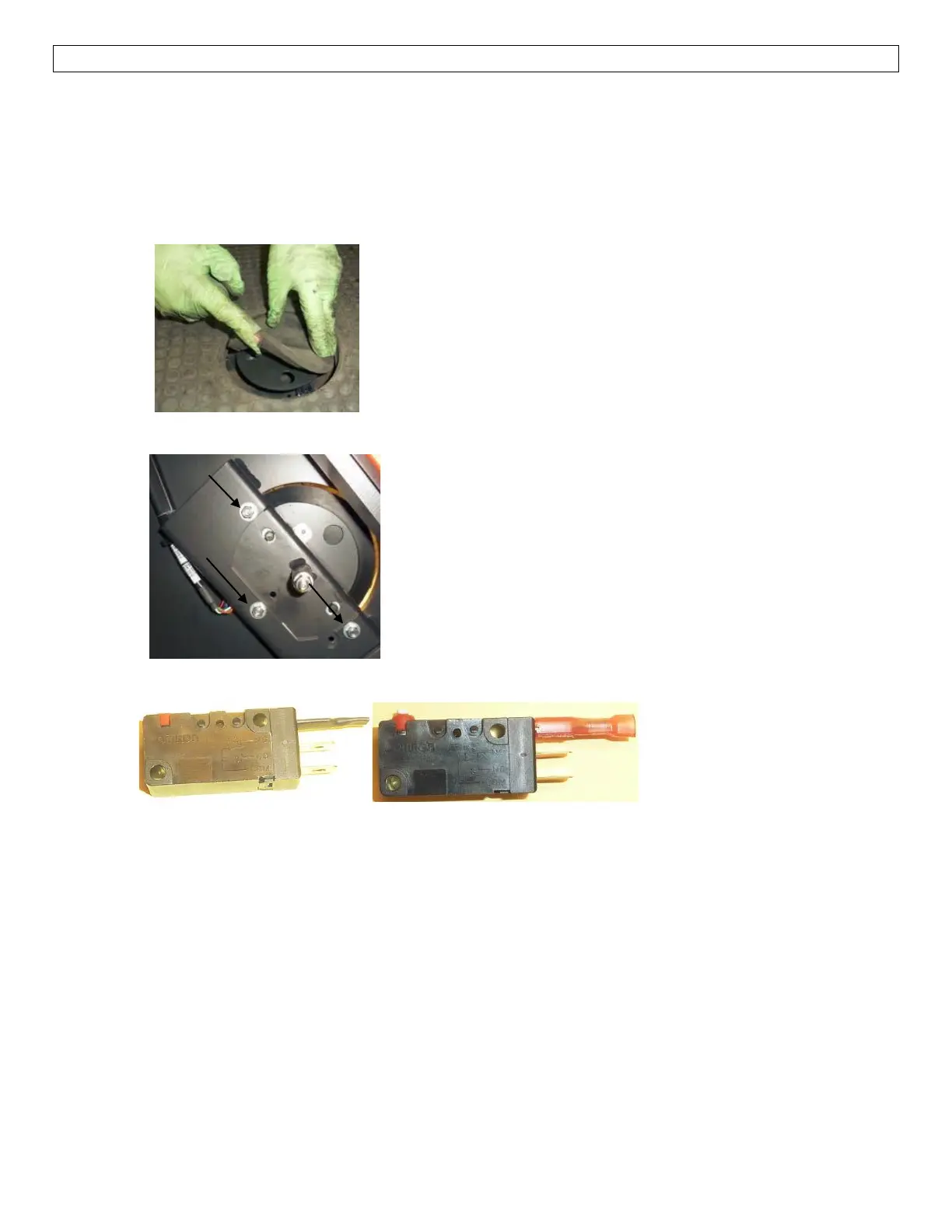
3. Remove the deadman pedal cover
4. Unplug electrical connector(s) at deadman switch(es).
5. Remove deadman pedal assembly.
6. The Normally Closed (NC) terminal of the new switch is not used. Cover it with shrink
tubing (item 4) or install a Faston terminal (item 2) to insulate it as shown below.
7. Remove old switch(es) and install new switch(es).
8. Reinstall deadman pedal assembly.
9. Cut wires at connector(s) that were plugged into the switch(es).
10. Strip wire insulation 0.25 in. (6.3 mm) and crimp a Faston terminal (item 2) on each wire.
NOTE: For S2, only the black and white wires are required. For S23, only the blue and green
wires are required.
11. Install shrink tubing (item 3) and embed the red wire (S2) and the orange wire (S23)
within the tubing.
12. Connect wires to the new switch(es) as follows:
a. S2 – connect the black wire to the “NO” terminal and the white wire to the “COM”
terminal.
b. S23 – connect the green wire to the “NO” terminal and the blue wire to the “COM”
terminal.
13. Secure the harness as necessary. Make sure it will not contact any moving parts.
14. Reinstall deadman pedal cover.
15. Connect the battery connector and turn the key switch ON.
16. Test deadman pedal for correct operation
 Loading...