Section
8.
Wire Guidance Toyota Orderpicker Model 7BPUE15 Service Manual
Install Kit Components
Load Sensor Assembly
1. Lift the platform, and securely place a
safety stand under the platform. Lower the
platform on the safety stand.
2.
Turn key switch OFF and disconnect the
battery.
3. Secure the antenna frame assembly
(P/N
00590
-
02772
-
71) to the cross tie between
the side cylinders with four hex head cap
screws. See Figure 8
-
3.
4. Connect the
1L
cable assembly (P/N
00590
-
029 1 1
-
7 1) to the connector on the
sensor assembly. See Figure 8
-
4.
Figure
8-4.
JW
I
Cable Connection
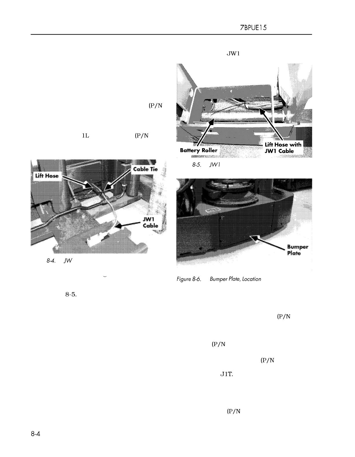
5. Route the cable along the lift hose to the
6. Connect the
JW1 cable to the filter card.
Figure
8-5.
JWI
Cable Routing Under Battery to Tractor
-
tractor. Add cable ties
loosely
as necessary
Figure
8-6.
Bumper Plate, location
to hold the cable to the hose. See
Figure
8-5.
Tractor Sensor Assembly
N
O
T
E
:
Tight cable ties will cause the shielded
1. Remove the bumper plate. See Figure 8
-
6.
sensor cable to break as the lift hose
expands when the platform lifts.
2. Place tractor sensor assembly
(P/N
00590
-
02842
-
7 1) on the bumper plate
with the connector jack facing the top of
the bumper plate and secure with four
screws
(P/N 00590
-
03085
-
7 1). See
Figure 8
-
7.
3. Connect cable assembly
(P/N
00590
-
45746
-
71) to the sensor at
connector
J1T.
See Figure 8
-
7.
4. Feed the cable through the cutout in the
tractor frame along the right side of the
tractor frame drive unit housing. Secure
the cable to the tractor frame using the
cable straps
(P/N 00590
-
03458
-
71) and
00700
-
CL222
-
05,
1
5
March 2005
 Loading...