Section 7. Component Procedures
Toyota Orderpicker Model
7BPUE 15 Service Manual
Control Handle
should be located in the slot furthest
7. Carefully unsolder the harness wires from
from the pin in the pot bracket.
the
lift/lower pot.
4. Remove the
lift/lower pot and bracket
from the cover. See Figure
7- 19.
Assembly
1. Carefully solder harness wires to the
proper terminals on the new
lift/lower pot.
,
Tab
Refer to
"
Hand Soldering Procedures
"
on
page 7
-
22.
Install horn switch assembly into the
handle cover by snapping the pin into the
plastic detents.
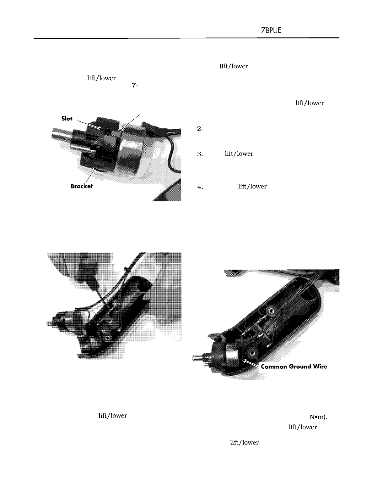
Slide
lift/lower pot bracket onto the shaft.
Make sure the anti
-
rotation tab is inserted
into the proper slot on the bracket. See
Figure 7
-
19.
Press the
lift/lower pot and bracket into
the handle cover. Make sure the key on the
bracket engages the keyway in the handle
Figure
7
-
19.
Anti
-
Rotate Tab
cover.
5.
Make sure all wires are routed properly.
5.
Carefully pry the horn switch from the
Tuck the common ground wire into handle
cover using a small screwdriver. See
between the bottom of the potentiometer
Figure 7
-
20.
and the screw boss to prevent the wire
from being pinched or interfering with the
horn button. See Figure 7
-
2 1.
Figure 7
-
20. Horn Switch Removal
N
O
T
E
:
The button, pin, and spring can easily
slide apart. Identify the proper position
of these components before
disassembly.
6.
If replacing the lift/lower pot, carefully
remove heat shrink tubing from the
terminals. Identify the wires so they can
be installed in the same location on the
new pot.
Figure 7
-
2
1.
Control Handle Wire Routing
6.
Install the cover onto the handle assembly
with the three socket head cap screws.
Torque to 15
-
20 in. lb. (1.7
-
2.25 N*m).
7. Install a fiber washer and lift/lower spring
(lightly greased with P/N 00590
-
04836
-
7 1)
on the
liftllower pot shaft. Install the
00700
-
CL222
-
05,
1
5
March 2005
 Loading...