Section 5. Troubleshooting Toyota Orderpicker Model
7BPUE
15 Service Manual
Switches (General)
Switches
(General)
Examine the switch for signs of arcing,
overheating, discoloration, cracking, or other
physical damage. Replace the switch if you see
such damage.
To test a switch, isolate it from the electrical
circuit. Do this by removing all the connections
from the switch, making sure all wires are
labeled and identified for reconnection.
Use an ohmmeter set to a low resistance scale
to measure the resistance across the switch. In
a closed position, the switch should be less
than 1 ohm. In an open position, the switch
should show a resistance greater than 10
megohms.
"1
$
q:;;
1
;,,lD~dman
DGND
Figure
5
-
1.
Hall Effect Switch Schematic
Hall
Effect Switches
The limit switches and deadman switches used
on this truck are Hall Effect switches. These
switches consist of a transistor that is turned
on when a magnet is positioned next to the
base. (Keep in mind that the magnet is part of
the switch assembly and can only be seen if the
switch is disassembled.)
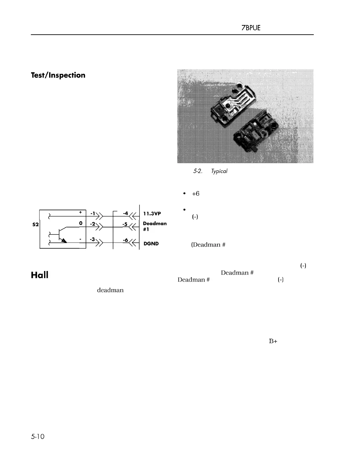
Figure
5-2.
Typical Hall Effect Switch
The switch is powered as follows:
+6
to
+
12 volts is applied to the positive
(+)
terminal.
Battery negative is applied to the negative
(-)
terminal.
As shown in Figure
5
-
1, when a magnet is not
present, the transistor is OFF and the output
lead
(Deadman
#
1) is in a high state.
When a magnet is present, the transistor is
turned ON creating a path from the DGND
(-)
terminal to the Deadman
#
1 terminal. Terminal
Deadman
#
1 will now be a negative
(-)
potential,
or active.
Key Switch
Inspection
With the battery plugged in and key switch in
the ON position, battery voltage
B+
should be
present on both terminals of the switch. Test
the key switch with an ohmmeter after
removing it from the electrical system. In the
OFF position, the ohmmeter should read
greater than 10 megohms, and in the ON
position, the ohmmeter should read less than 1
ohm. If not, replace the switch.
00700
-
CL222
-
05,
1
5
March 2005
 Loading...