FRONT ARMS AND FRONT SHOCK ABSORBER ASSEMBLIES
4-53
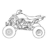
d. Hold the body “4” in place while turning in the
long bolt “5” to remove the ball joint “10” from
the front lower arm “11”.
e. Remove the ball joint remover/installer.
f. Attach the assembled ball joint remover/in-
staller, new ball joint (with rubber boot and re-
taining ring) “12”, installer spacer “8” and
installer washer “9” to the front lower arm
“11”.
IP
• Do not tap or damage the top of the ball joint.
• Installer spacer “8” must be aligned with the
projection on the head of the ball joint “12”.
g. Remove the ball joint remover/installer.
h. Install a new circlip.
IP
Always use a new ball joint set.
▲▲▲▲▲▲▲▲▲ ▲ ▲▲▲▲ ▲ ▲▲▲▲ ▲ ▲▲▲▲ ▲ ▲▲▲▲ ▲▲▲
EAS29790
INSTALLING THE FRONT ARMS AND
FRONT SHOCK ABSORBER ASSEMBLIES
The following procedure applies to both of the
front upper arms, front lower arms, and front
shock absorber assemblies.
1. Install:
• Front upper arm
• Front lower arm
• Front shock absorber assembly
▼▼▼▼▼▼▼▼▼ ▼ ▼▼▼▼ ▼ ▼▼▼▼ ▼ ▼▼▼▼ ▼ ▼▼▼▼ ▼▼▼
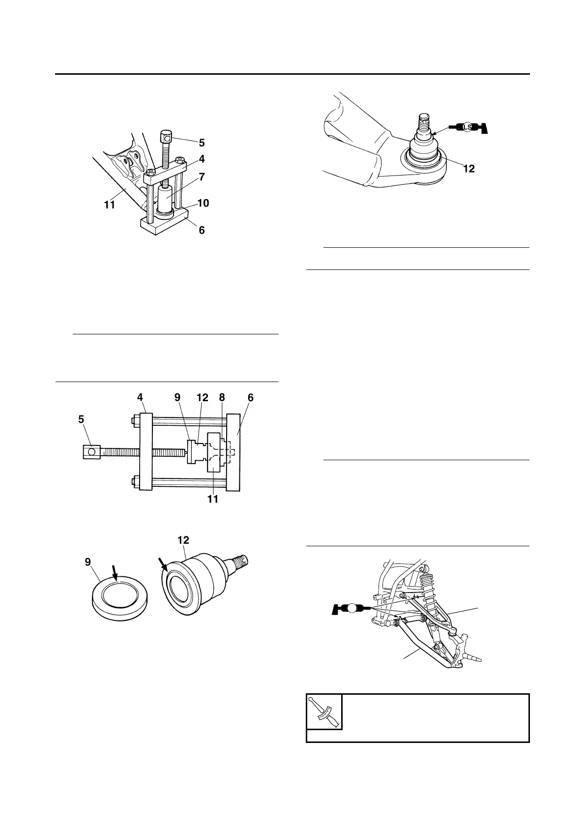
a. Install the front upper arm “1” and front lower
arm “2”.
IP
• Be sure to position the front upper and lower
arm bolts so that the bolt heads face forward.
• Temporarily tighten the front upper and lower
arm nuts.
• Apply lithium-soap-based grease to the grease
nipple.
b. Install the front shock absorber assembly.
c. Install the steering knuckle.
T
R
.
.
Front shock absorber assembly
nut
48 Nm (4.8 m·kg, 35 ft·lb)
LS
2
1
 Loading...