SHIFT SHAFT
5-55
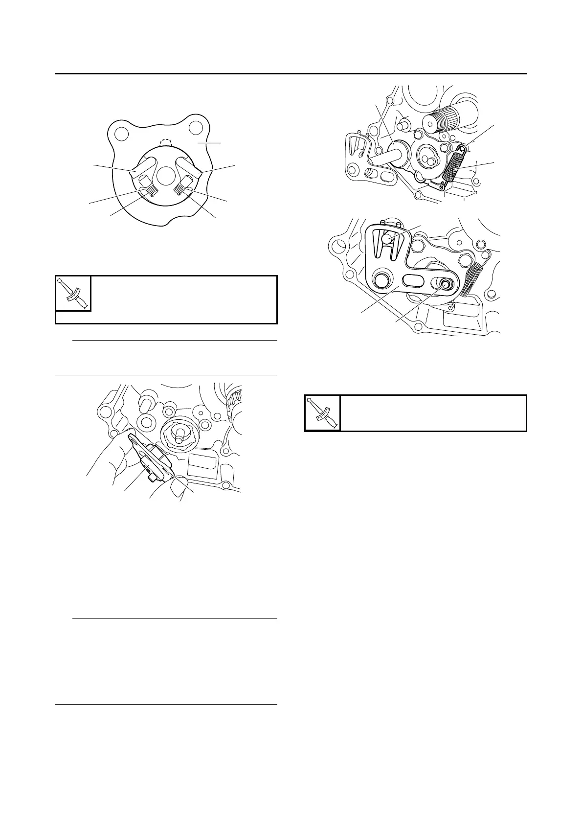
• Shift guide “4”
(to the pawl holder)
3. Install:
• Shift lever assembly “1”
• Shift guide “2”
IP
The shift lever assembly is installed at the same
time as the shift guide.
EAS25450
INSTALLING THE SHIFT SHAFT
1. Install:
• Stopper lever “1”
• Stopper lever spring “2”
• Shift shaft “3”
• Roller “4”
• Shift shaft spring
IP
• Hook the ends of the stopper lever spring onto
the stopper lever and the crankcase boss “5”.
• Install the end of the shift shaft spring onto the
shift shaft spring stopper “6”.
• Install the end of the shift shaft lever onto the
roller “4”.
2. Install:
• Shift pedal
Refer to “ADJUSTING THE SHIFT PEDAL”
on page 3-25.
T
R
.
.
Shift guide bolt
10 Nm (1.0 m·kg, 7.2 ft·lb)
LOCTITE®
4
3
3
2
2
1
1
1
2
T
R
.
.
Shift pedal bolt
16 Nm (1.6 m·kg, 11 ft·lb)
1
5
2
4
3
6
 Loading...