ENGINE
3-4
EAS20472
ENGINE
EAS20520
ADJUSTING THE VALVE CLEARANCE
The following procedure applies to all of the
valves.
IP
• Valve clearance adjustment should be made
on a cold engine, at room temperature.
• When the valve clearance is to be measured or
adjusted, the piston must be at top dead center
(TDC) on the compression stroke.
1. Remove:
• Seat
• Front fender
• Fuel tank
Refer to “GENERAL CHASSIS” on page 4-1.
2. Remove:
• Intake tappet cover
• Exhaust tappet cover “1”
• Camshaft sprocket cover “2”
3. Disconnect:
• Spark plug cap “1”
4. Remove:
• Spark plug “2”
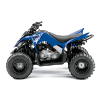
5. Remove:
• Timing mark accessing screw “1”
• Crankshaft end accessing screw “2”
6. Measure:
• Valve clearance
Out of specification → Adjust.
▼▼▼▼▼▼▼▼▼ ▼ ▼▼▼▼ ▼ ▼▼▼▼ ▼ ▼▼▼▼ ▼ ▼▼▼▼ ▼▼▼
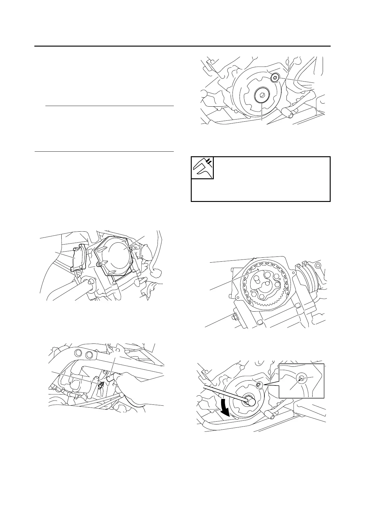
a. Turn the crankshaft counterclockwise.
b. When the piston is at TDC on the compres-
sion stroke, align the punch mark “a” in the
camshaft sprocket with the stationary pointer
“b” on the cylinder head.
c. Align the TDC mark “c” on the AC magneto
rotor with the stationary pointer “d” on the AC
magneto cover.
d. Measure the valve clearance with a thickness
gauge “1”.
Out of specification → Adjust.
2
1
2
1
Valve clearance (cold)
Intake
0.09–0.13 mm (0.0035–0.0051 in)
Exhaust
0.16–0.20 mm (0.0063–0.0079 in)
1
2
b
a
c
d
 Loading...