ELECTRICAL COMPONENTS
8-65
EAS28040
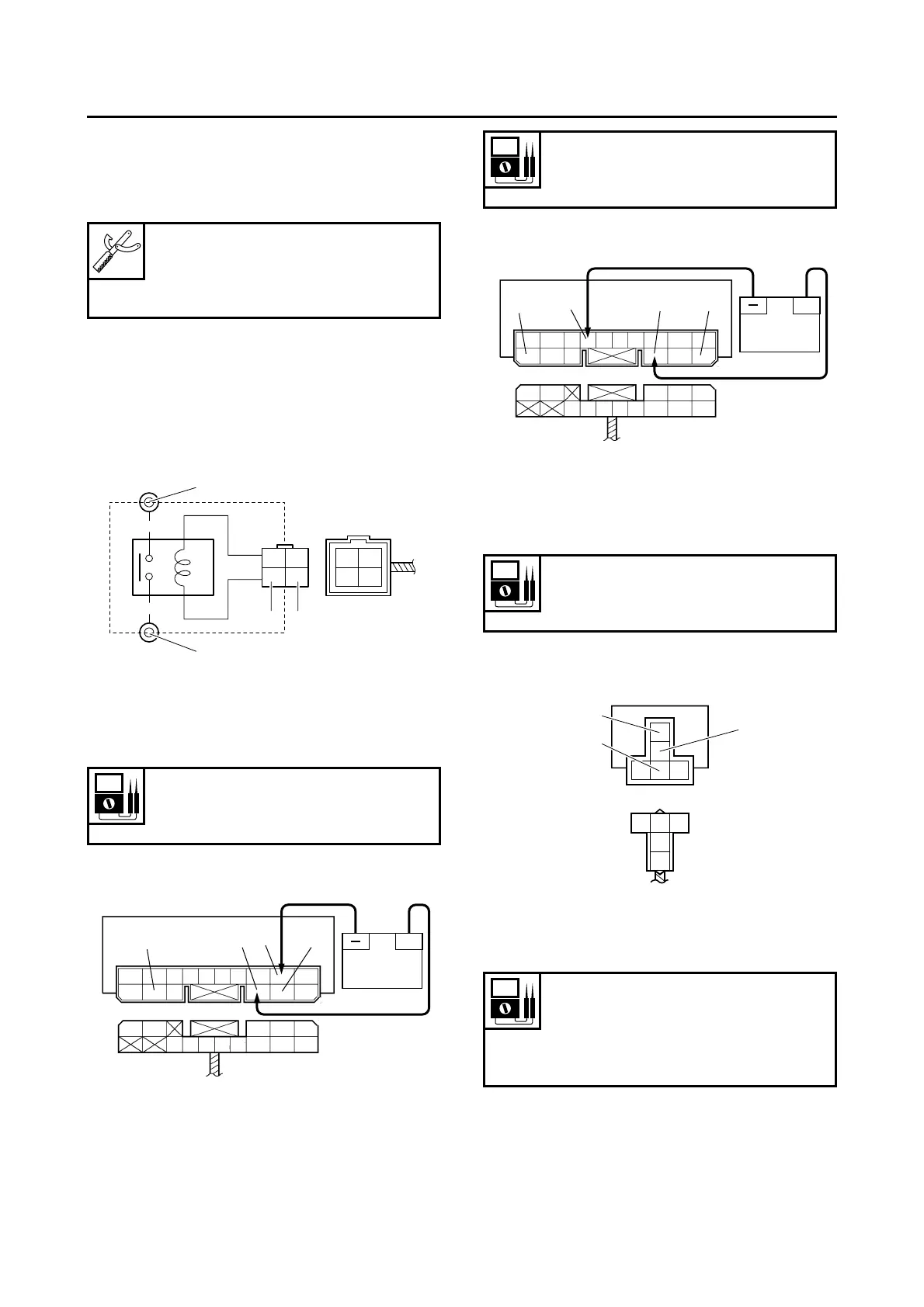
CHECKING THE RELAYS
Check each switch for continuity with the pocket
tester. If the continuity reading is incorrect, re-
place the relay.
1. Disconnect the relay from the wire harness.
2. Connect the pocket tester (Ω × 1) and battery
(12 V) to the relay terminal as shown.
Check the relay operation.
Out of specification → Replace.
Starter relay
Relay unit (starting circuit cut-off relay)
Relay unit (fuel pump relay)
Headlight relay
First step:
Pocket tester
90890-03112
Analog pocket tester
YU-03112-C
1. Positive battery terminal
2. Negative battery terminal
3. Positive tester probe
4. Negative tester probe
Result
Continuity
(between “3” and “4”)
1. Positive battery terminal
2. Negative battery terminal
3. Positive tester probe
4. Negative tester probe
RR
L/W
Br
R
B
12
4
3
+
3
1
2
4
L/WL/RL/GL/Y
B/Y
L/W
R/BL/BR/L
Br/G
Br Sb Lg
Result
Continuity
(between “3” and “4”)
1. Positive battery terminal
2. Negative battery terminal
3. Positive tester probe
4. Negative tester probe
Result
Continuity
(between “3” and “4”)
1. Positive tester probe
2. Negative tester probe
3. Negative tester probe
Result
Continuity
(between “1” and “2”)
No continuity
(between “1” and “3”)
+
3
1
2
4
L/WL/RL/GL/Y
B/Y
L/W
R/BL/BR/L
Br/G
Br Sb Lg
L
Y
GBY
2
3
1
 Loading...