AND
AND
AND
bus1Voltage
OR
OR
OR
ULN1FF
ULN1OK
UB1FF
UB1OK
UB2FF
UB2OK
B2QCLD
B2QOPEN
B1QCLD
B1QOPEN
BLOCK
bus2Voltage
AND
1
B2SEL
B1SEL
AND
AND
AND
USELFAIL
en05000779-2.vsd
OR
invalidSelection
busVoltage
selectedFuseOK
IEC05000779 V2 EN
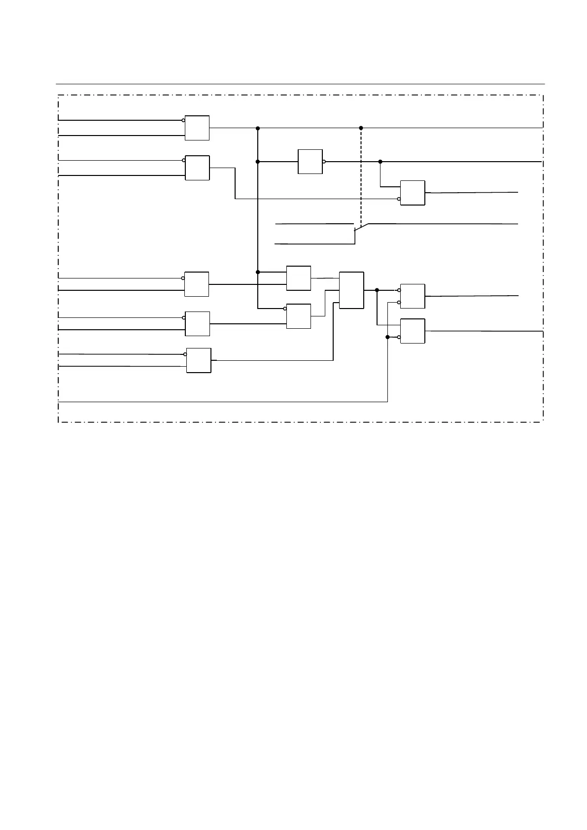
Figure 99: Logic diagram for the voltage selection function of a single circuit breaker with double busbars
10.1.7.8 Voltage selection for a 1 1/2 circuit breaker arrangement
Note that with 1½ breaker schemes three Synchrocheck functions must be used for the
complete diameter. Below, the scheme for one Bus breaker and the Tie breaker is
described.
This voltage selection function uses the binary inputs from the disconnectors and
circuit breakers auxiliary contacts to select the right voltage for the SESRSYN
(Synchronism, Synchronizing and Energizing check) function. For the bus circuit
breaker one side of the circuit breaker is connected to the busbar and the other side is
connected either to line 1, line 2 or the other busbar depending on the best selection of
voltage circuit.
Inputs LN1QOPEN-LN1QCLD, B1QOPEN-B1QCLD, B2QOPEN-B2QCLD,
LN2QOPEN-LN2QCLD are inputs for the position of the Line disconnectors
respectively the Bus and Tie breakers. The outputs LN1SEL, LN2SEL and B2SEL
will give indication of the selected Line voltage as a reference to the fixed Bus 1
voltage, which indicates B1SEL.
1MRK 511 287-UEN A Section 10
Control
221
Technical manual
 Loading...