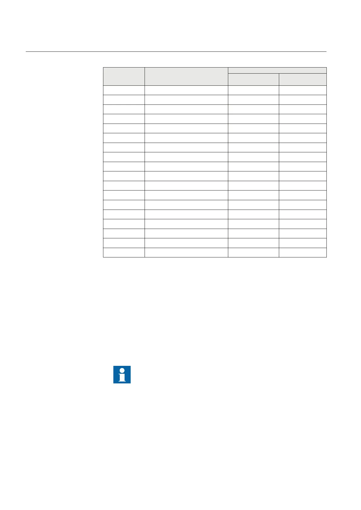
Table 538: Binary inputs X339, 3U full 19”
Terminal Description PCM600 info
Hardware module
instance
Hardware channel
X339-1 - for input 1 BIO_6 BI1
X339-2 Binary input 1 + BIO_6 BI1
X339-3 -
X339-4 Common - for inputs 2-3
X339-5 Binary input 2 + BIO_6 BI2
X339-6 Binary input 3 + BIO_6 BI3
X339-7 -
X339-8 Common - for inputs 4-5
X339-9 Binary input 4 + BIO_6 BI4
X339-10 Binary input 5 + BIO_6 BI5
X339-11 -
X339-12 Common - for inputs 6-7
X339-13 Binary input 6 + BIO_6 BI6
X339-14 Binary input 7 + BIO_6 BI7
X339-15 -
X339-16 Common - for inputs 8-9
X339-17 Binary input 8 + BIO_6 BI8
X339-18 Binary input 9 + BIO_6 BI9
16.3 Outputs
16.3.1 Outputs for tripping, controlling and signalling
Output contacts PO1, PO2 and PO3 are power output contacts used, for example, for
controlling circuit breakers.
Each signal connector terminal is connected with one 0.5...2.5 mm
2
wire or with two
0.5...1.0 mm
2
wires.
The connected DC voltage to outputs with trip circuit supervision
(TCS) must have correct polarity or the trip circuit supervision
TCSSCBR function will not operate properly.
Section 16 1MRK 511 287-UEN A
IED physical connections
592
Technical manual
 Loading...