GUID-82C88B52-1812-477F-8B1A-3011A300547A V1 EN
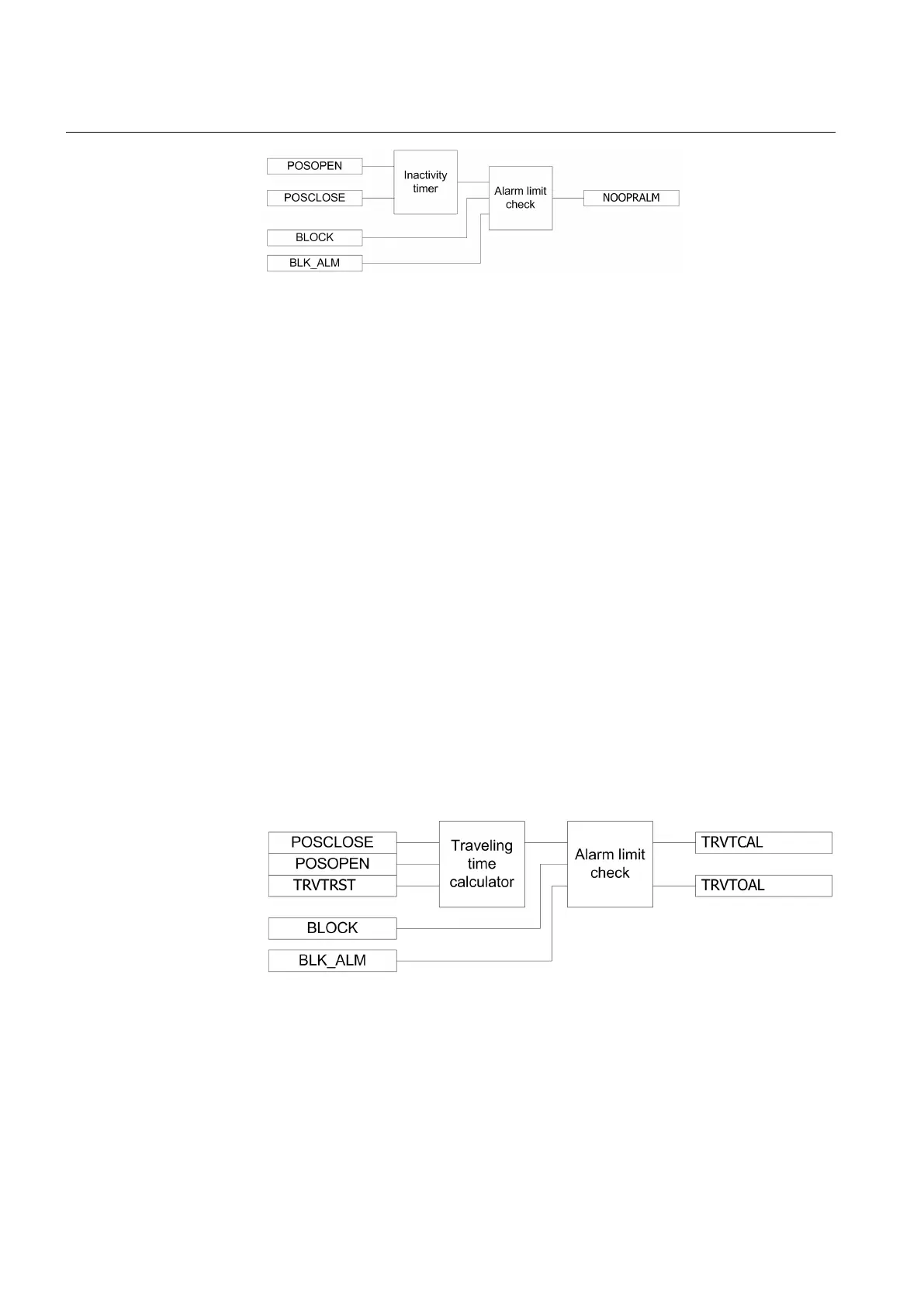
Figure 233: Functional module diagram for calculating inactive days and alarm
for circuit breaker operation monitoring
Inactivity timer
The module calculates the number of days the circuit breaker has remained inactive,
that is, has stayed in the same open or closed state. The calculation is done by
monitoring the states of the POSOPEN and POSCLOSE auxiliary contacts.
The inactive days NOOPRDAY is available through the Monitored data view. It is also
possible to set the initial inactive days by using the InactDayInit parameter.
Alarm limit check
When the inactive days exceed the limit value defined with the InactDayAlm setting,
the NOOPRALM alarm is initiated. The time in hours at which this alarm is activated
can be set with the InactHourAlm parameter as coordinates of UTC. The alarm signal
NOOPRALM can be blocked by activating the binary input BLOCK.
12.18.7.3 Breaker contact travel time
The breaker contact travel time module calculates the breaker contact travel time for
the closing and opening operation. The operation of the breaker contact travel time
measurement can be described by using a module diagram. All the modules in the
diagram are explained in the next sections.
GUID-4D82C157-53AF-40C9-861C-CF131B49072B V1 EN
Figure 234: Functional module diagram for breaker contact travel time
Travelling time calculator
The breaker contact travel time is calculated from the time between auxiliary contacts'
state change. The open travel time is measured between the opening of the
POSCLOSE auxiliary contact and the closing of the POSOPEN auxiliary contact.
Section 12 1MRK 511 287-UEN A
Monitoring
494
Technical manual
 Loading...