R
1A
+jX
1A
R
0L
+jX
0L
R
1L
+jX
1L
R
1B
+jX
1B
IEC09000726_1_en.vsd
DRPRDRE
LMBRFLO
IEC09000726 V1 EN
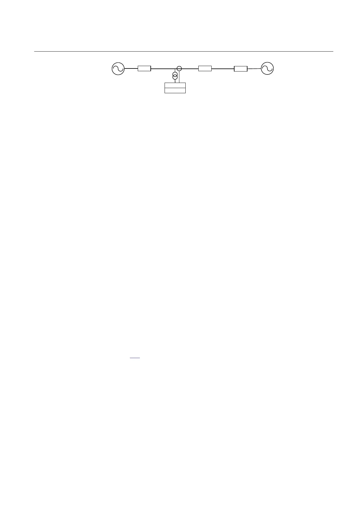
Figure 224: Simplified network configuration with network data, required for
settings of the fault location-measuring function
If source impedance in the near and far end of the protected line have changed in a
significant manner relative to the set values at fault location calculation time (due to
exceptional switching state in the immediate network, power generation out of order,
and so on), new values can be entered via the local HMI and a recalculation of the
distance to the fault can be ordered using the algorithm described below. It’s also
possible to change fault loop. In this way, a more accurate location of the fault can be
achieved.
The function indicates the distance to the fault as a percentage of the line length, in
kilometers or miles as selected on the local HMI. LineLengthUnit setting is used to
select the unit of length either, in kilometer or miles for the distance to fault. Line
length unit can also be configured using PCM600. The fault location is stored as a part
of the disturbance report information and managed via the LHMI or PCM600.
12.14.7.1 Measuring Principle
For transmission lines with voltage sources at both line ends, the effect of double-end
infeed and additional fault resistance must be considered when calculating the
distance to the fault from the currents and voltages at one line end. If this is not done,
the accuracy of the calculated figure will vary with the load flow and the amount of
additional fault resistance.
The calculation algorithm used in the fault locator in compensates for the effect of
double-end infeed, additional fault resistance and load current.
12.14.7.2 Accurate algorithm for measurement of distance to fault
Figure
225 shows a single-line diagram of a single transmission line, that is fed from
both ends with source impedances Z
A
and Z
B
. Assume that the fault occurs at a
distance F from IED A on a line with the length L and impedance Z
L
. The fault
resistance is defined as R
F
. A single-line model is used for better clarification of the
algorithm.
1MRK 511 287-UEN A Section 12
Monitoring
475
Technical manual
 Loading...