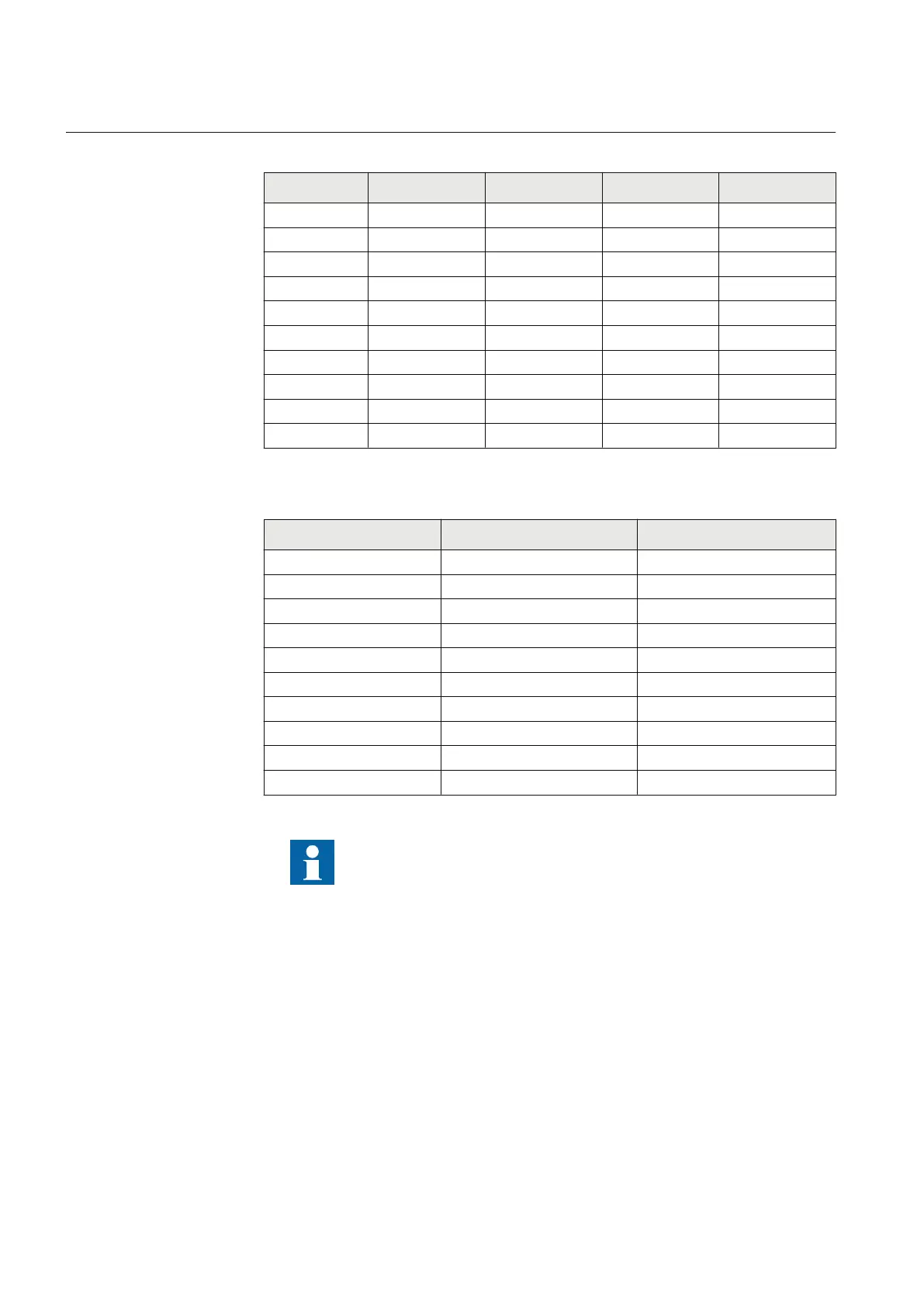
Table 529: Analog input modules TRM
Terminal TRM
6I + 4U
TRM
8I + 2U
TRM
4I + 1I + 5U
TRM
4I + 6U
X101-1, 2 1/5A 1/5A 1/5A 1/5A
X101-3, 4 1/5A 1/5A 1/5A 1/5A
X101-5, 6 1/5A 1/5A 1/5A 1/5A
X101-7, 8 1/5A 1/5A 1/5A 1/5A
X101-9, 10 1/5A 1/5A 0.1/0.5A 100/220V
X102-1, 2 1/5A 1/5A 100/220V 100/220V
X102-3, 4 100/220V 1/5A 100/220V 100/220V
X102-5, 6 100/220V 1/5A 100/220V 100/220V
X102-7, 8 100/220V 100/220V 100/220V 100/220V
X102-9, 10 100/220V 100/220V 100/220V 100/220V
Table 530: Analog input modules AIM
Terminal AIM
6I + 4U
AIM
4I + 1I + 5U
X103-1, 2 1/5A 1/5A
X103-3, 4 1/5A 1/5A
X103-5, 6 1/5A 1/5A
X103-7, 8 1/5A 1/5A
X103-9, 10 1/5A 0.1/0.5A
X104-1, 2 1/5A 100/220V
X104-3, 4 100/220V 100/220V
X104-5, 6 100/220V 100/220V
X104-7, 8 100/220V 100/220V
X104-9, 10 100/220V 100/220V
See the connection diagrams for information on the analog input
module variant included in a particular configured IED. The primary
and secondary rated values of the primary VT's and CT's are set for the
analog inputs of the IED.
16.2.2 Auxiliary supply voltage input
The auxiliary voltage of the IED is connected to terminals X420-1 and X420-2/3. The
terminals used depend on the power supply.
The permitted auxiliary voltage range of the IED is marked on top of the IED's LHMI.
Section 16 1MRK 511 287-UEN A
IED physical connections
588
Technical manual

 Loading...