4 Individual remote controls
PC-ART
TCGB0106 rev.0 - 12/2014
145
4
H5 Central control available after forced stoppage.
This function is used in order allow the central control when unit is forced to stop.
When this function is “01”, the central control is available.
4.2.7 Maintenance and repair
4.2.7.1 Abnormal transmission between the remote control and indoor unit
In this case, the LED run indicator located at the bottom left of the screen will ash every 2 seconds.
DANGER
Before analysing these problems, the system must be switched off at the mains.
Problem Cause Check point Action
Disconnection or inadequate
contact of the remote control
cable.
Cabling problem
Check the cable and the connec-
tions.
Repair or connect the cable.
Remote control fault. Different causes
Check remote control using the self-
check mode
*1
.
Replace the remote control, if faulty.
PCB fault (on the indoor unit and
remote control).
Wire disconnected
from PCB
Check connectors. Connect wires correctly.
PCB fault
Check PCB using the self-check
mode
*2
.
Change the PCB, if faulty.
*1: See section Remote control self-checking procedure.
*2: See section Checking procedure for each main component.
4.2.7.2 Troubleshooting procedure for units connected to the remote control
Possible causes:
• The remote control cable is broken.
• Remote control cable contact failure.
• Remote control plate failure.
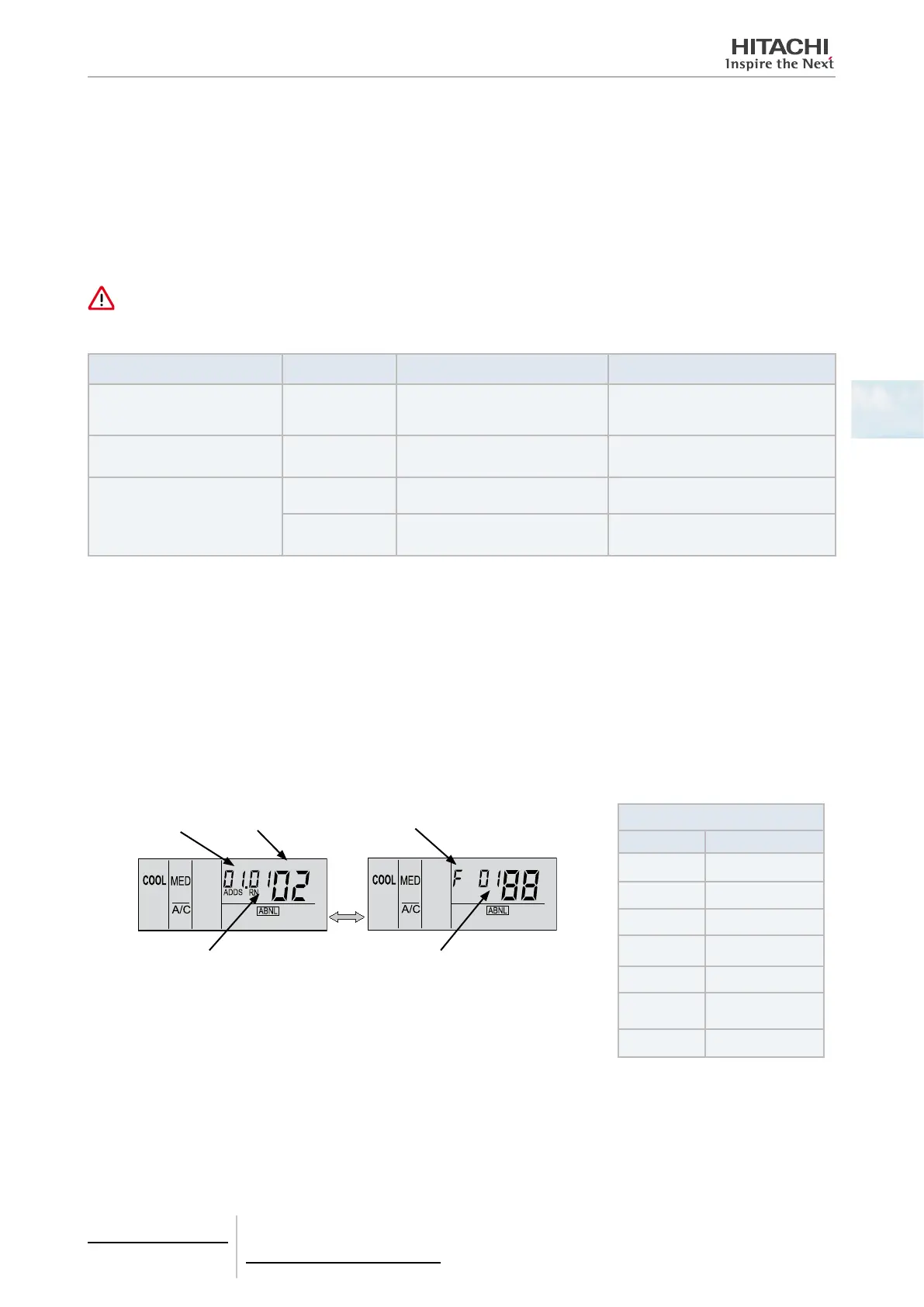
• If the LED run indicator ashes 5 times for 5 seconds, the display will show the unit number and alarm code.
• Note down the code (see table) and request assistance from your distributor.
Unit number Alarm code Model code
Refrigerant cycle number Number of units connected
Model number
Indication Model
H
Heat pump
P
Inverter
F
Multiple
C
Cooling only
E
Other
b
IVX, individual
operation
L
KPI
The Alarm code corresponds to the alarm that is happening on the unit.
Refer to the Service Manual of the unit to know the meaning of the alarm code.

 Loading...