7 Gateways for building management systems
HARC-BX E
TCGB0106 rev.0 - 12/2014
675675
7
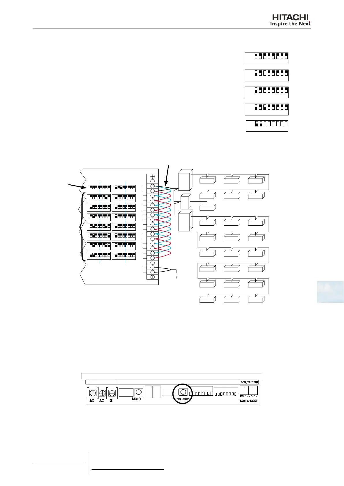
5 Set the 8 pin DIP switch (S202). The 8 pin DIP switch (S202) is used as follows:
Board not activated
ON 1 2 3 4 5 6 7 8
Activate the board to control a given number of indoor units based on S201
ON 1 2 3 4 5 6 7 8
Board active as slave
ON 1 2 3 4 5 6 7 8
Board active master (only one board can be a master board on each H-Link line)
ON 1 2 3 4 5 6 7 8
Test Mode for the activated board (see section Test Mode for further details)
ON 1 2 3 4 5 6 7 8
DIP programming example:
The following diagram shows an example for connecting a HARC-BX(B) on an installation:
OU 0
IU 00 IU 01 IU 02
IU 03 IU 04 IU 05
OU 1
IU 00
OU 2
(OU 3)
IU 00 IU 01 IU 02
IU 03 IU 04 IU 05
IU 06 IU 07 IU 08
IU 09 IU 10 IU 11
IU 12 IU 13 IU 14
IU 15 IU 00 IU 01
O
N
1 2
3
4
5
6
7 8
O
N
1 2
3
4
5
6
7 8
O
N
1 2
3
4
5
6
7 8
O
N
1 2
3
4
5
6
7 8
O
N
1 2
3
4
5
6
7 8
O
N
1 2
3
4
5
6
7 8
O
N
1 2
3
4
5
6
7 8
O
N
1
2
3
4
5
6
7 8
O
N
1 2
3
4
5
6
7 8
O
N
1 2
3
4
5
6
7 8
O
N
1 2
3
4
5
6
7 8
O
N
1 2
3
4
5
6
7 8
O
N
1 2
3
4
5
6
7 8
O
N
1 2
3
4
5
6
7 8
O
N
1 2
3
4
5
6
7 8
O
N
1 2
3
4
5
6
7 8
1
2
3
4
5
6
7
8
N
OU
IU
N
U
Master
board
Slave
boards
H-Link connection
IU: Indoor Unit
OU: Outdoor Unit
7.4.3.5 BMS connection
Take the following points into account for the correct connection of the BMS:
- The correct electric wiring as indicated in previous sections.
- The BMS protocol:
- The BMS should update its hardware via LonWorks as shown previously.
- BMS start up:
- Press the LON.SERV button:
- When this button is pressed, the HARC-BX E sends the “Neuron Chip ID” identication.
- The communication starts at that moment and the BMS can read and receive orders.
- BMS troubleshooting is the responsibility of the BMS itself.

 Loading...