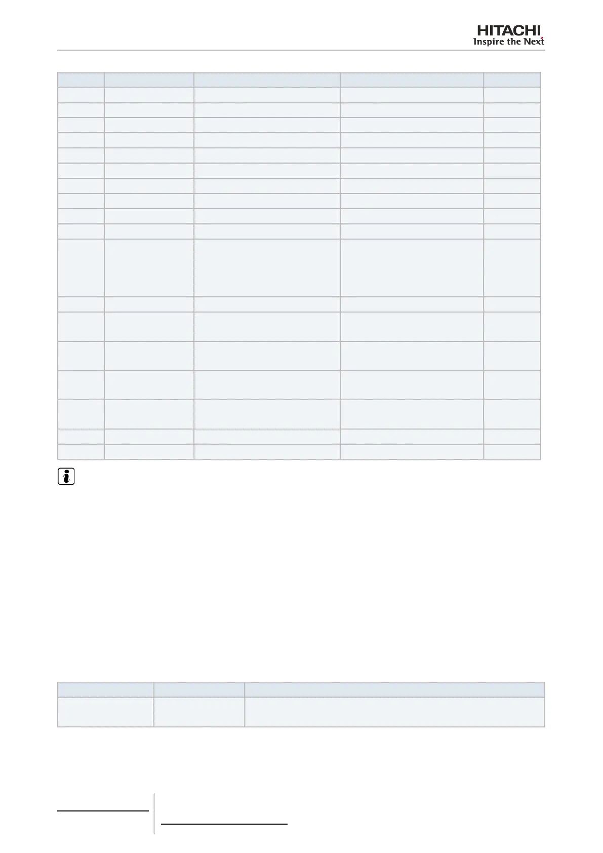
Offset (1) Name Description Values Read/Write
12 READ_TSET Setting temperature status 17ºC ~ 30ºC Read
13 READ_LOUVER Louver status 0 ~ 7 (7 is Auto) Read
14 (Not used) (Not used) (Not used) (Not used)
15 TIN Inlet temperature reading (2) -63ºC ~ 63ºC Read
16 TOUT Outlet temperature reading (2) -63ºC ~ 63ºC Read
17 TGAS Gas pipe temperature reading (2) -63ºC ~ 63ºC Read
18 TLIQUID Liquid pipe temperature reading (2) -63ºC ~ 63ºC Read
19 ERROR_CODE Alarm code Alarm unit from 7-segment Read
20 STOP_CAUSE Compressor stop cause (Read unit service manual) Read
21 VALVE_OPEN Indoor unit expansion valve opening 0~100 (Not used)
22 OPER_CONDITION Unit operation condition
0: OFF
1: Thermo OFF
2: Thermo ON
3: Alarm
Read
23 (Not used) (Not used) (Not used) (Not used)
24
AMBIENT TEMPERA-
TURE
Ambient temperature (2) -63ºC ~ 63ºC Read
25 RCS_TEM
Remote control switch temperature
(only when available in the unit) (2)
-63ºC ~ 63ºC Read
26 RCS_CONFIG Remote control switch conguration
b0: 0 Master / 1 Slave
b1: 0 wih RCS / 1 Without RCS
Read/Write
27 RCS_GROUP Remote control switch group
0: No group
1~255
Read/Write
28~30 (Not used) (Not used) (Not used) (Not used)
31 REM_TEM Remote sensor temperature (2) -63ºC ~ 63ºC Read
NOTE
• (1): Register address is calculated as: “N + (Address * 32) + Offset” where:
- N: Data table position is 2000, position 20000 is also available to maintain compatibility with old Modbus gateway.
- Address: Indoor unit address as congured by conguration software.
• (2): These numbers refer to signed 16-bit value using 2-complement format for negative values.
• (3): Bit 0 (ON/OFF) and Bit 4 (Louver) selectable only when all centrals are activated. In order to full lock setting from RCS (Central
shown in RCS) set this register to 31.
7.1.5 Alarm code
Address 19 indicates alarm code as shown in indoor unit. Refer to Service Manual for the alarm explanation and repair
procedure in case of Indoor Unit or Outdoor Unit alarm.
7.1.6 Troubleshooting
ALARM CODE DESCRIPTION COUNTERMEASURE
LED2 is ickering Abnormal operation
Shut down the device power supply and restore it after 5 s. If LED2 is still icker-
ing contact to the HITACHI customer service
7 Gateways for building management systems
HC-A(8/64)MB
TCGB0106 rev.0 - 12/2014
634634

 Loading...