7 Gateways for building management systems
KNX001
TCGB0106 rev.0 - 12/2014
650650
7.3.2.7 Installation procedure
1 Ensure that there is no power supply connected to any part of KNX001 (power terminals and EIB bus).
2 Install the device following the detailed explanations in 4.2.1 and 4.2.2. It is recommended to install KNX001 inside an
electrical box.
3 Connect current adaptor to the KNX001 keeping right polarity (see technical characteristics for power supply connec-
tions).
4 Connect CSNET WEB to KNX001 by ETH connector. CSNET WEB connection can be done directly by ethernet
crossed cable CAT5 or directly from LAN installation of the building. In the last case used non crossed ethernet CAT5
cable in order to connect KNX001. Consult to computer net administrators for TCP connection. KNX001 is connected
to CSNET WEB by port 502.
5 Connect EIB bus to KNX TP1 (EIB) and keep correctly polarity.
6 Connect current adaptor to the power net.
7 Provide power to EIB bus.
8 Follow the instructions in TCXX0055_rev0 attached inside of CD ROM for KNX001 conguration and start up.
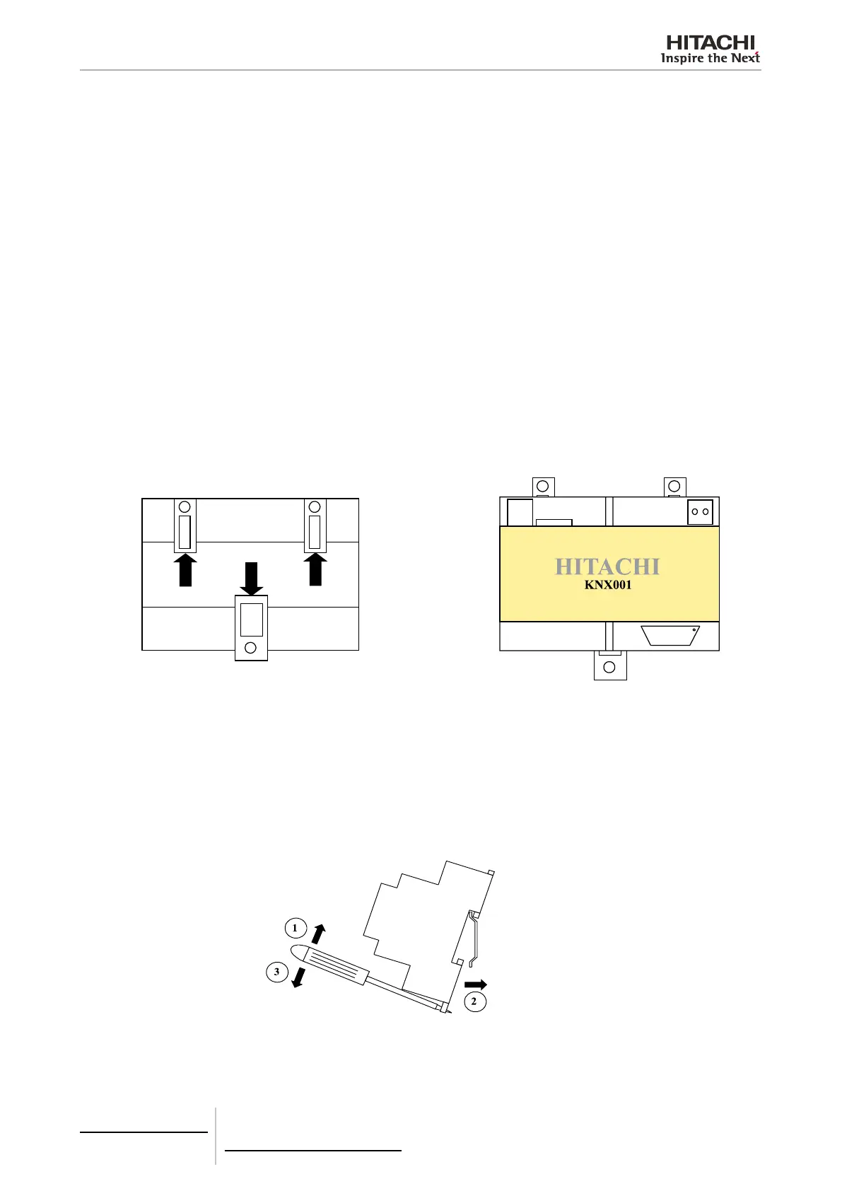
Wall Assembly
Pull the upper plastic parts and lower plastic part outside until xing holes are visible from front side and a ‘click’ is heard
(see right gure below).
Back side view Front side view
Plastic parts positioned for rail DIN assembly Plastic parts ready for wall assembly
Use the holes of the plastic parts for wall mounting.
Rail DIN Assembly
Hang upper side of the device from the upper side of DIN prole. Using a screwdriver pull the lower plastic part (see draw-
ing) and push the lower side of the device against the prole.
Side view

 Loading...