8
8.5 PC-AMTB
8.5.1 Safety summary
NOTE
• HITACHI cannot anticipate every possible circumstance that might involve a potential hazard.
• Read carefully this document before performing the installation work.
DANGER
• Do not install this device in places accessible to the general public. Install it in enclosures or other places which not are
accessible.
• Do not connect power supply before the device installation is correctly done. Always disconnect power supply from the
device before any maintenance or servicing action.
C AUTION
• The device installation must be performed by qualied professionals.
• Check to ensure that the eld supplied electrical components (mains power switches, circuit breakers, wires, connectors and wire
terminals) have been properly selected according to the electrical data indicated on this document and they comply with national and
local codes. If it is necessary, contact with your local authority in regards to standards, rules, regulations, etc.
• This appliance must be used only by adult and capable people, having received the technical information or instructions to handle
properly and safely this appliance.
• Children should be supervised to ensure that they do not play with the appliance.
8.5.2 Installation
8.5.2.1 Installation site selection
Take note of the maximum admissible cable length between units and the control as well as between the units themselves,
as shown in the following table:
Cable section 0.3 mm
2
≥ 0.75 mm
2
Cable length 30 m 500 m
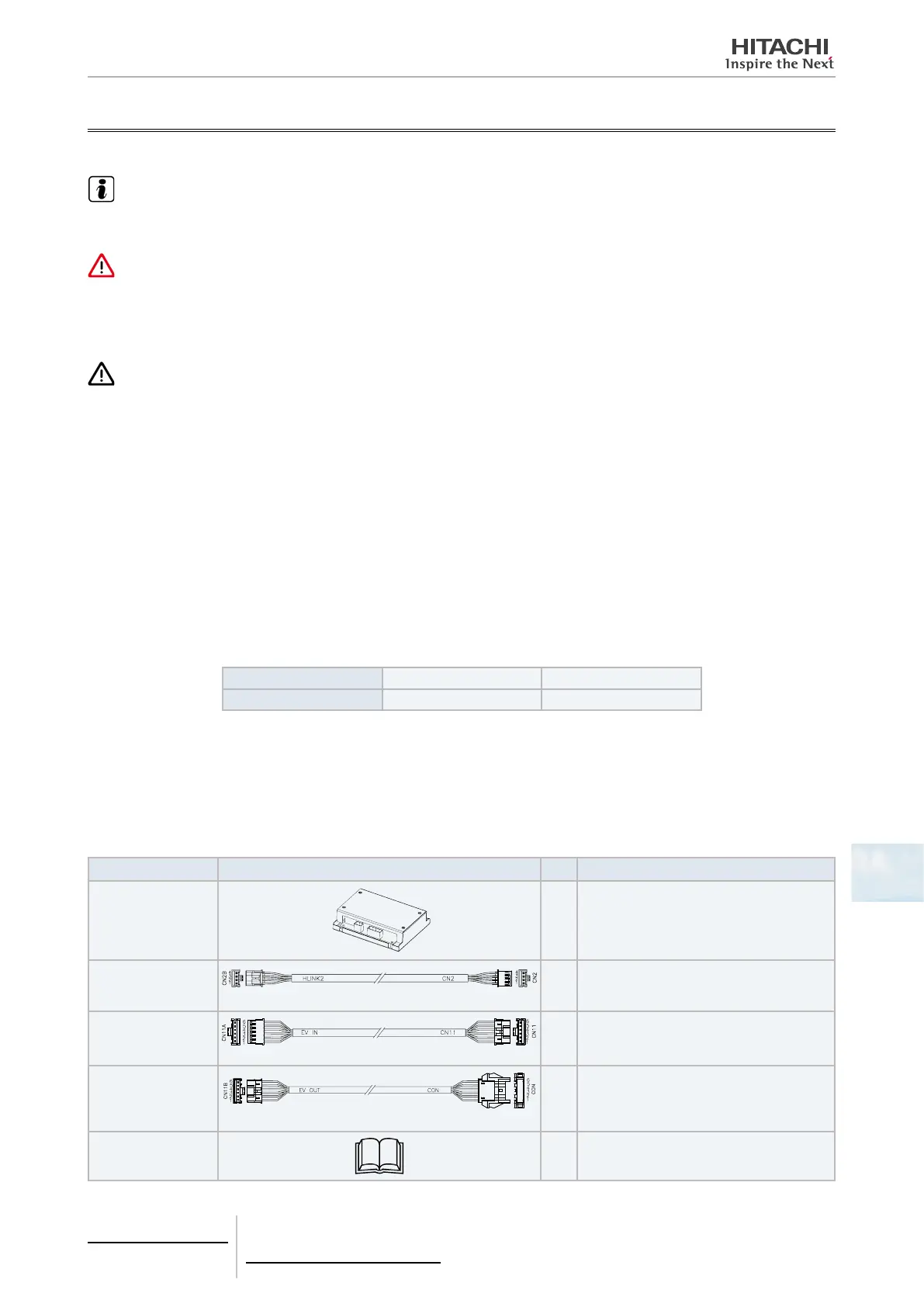
8.5.2.2 Components list
Unpack the unit and check that:
• The package contains all the components (see next table).
• All components are in perfect condition.
Otherwise, contact the manufacturer.
Item Description Qty. Purpose
Multitenant Box
1
For allowing individual shutdown of indoor
units in a multiple indoor unit installation.
Connector wire <1>
Red
Red
1
For the electrical connection between
“H-LINK2” connector of PC-AMTB and the
“CN2” connector of Indoor unit PCB.
Connector wire <2>
White
White
1
For the electrical connection between “EV
IN” connector of PC-AMTB and the “CN11”
connector of Indoor unit PCB.
Connector wire <3>
Red White
1
For the electrical connection between “EV
OUT” connector of PC-AMTB and the EVI
wire-end previously connected to the “CN11”
connector of indoor unit PCB.
Installation and op-
eration manual
1 Installation and operation unit instructions.
8 Control support devices
PC-AMTB
TCGB0106 rev.0 - 12/2014
737

 Loading...