4 Individual remote controls
PC-ART
TCGB0106 rev.0 - 12/2014
154
Step
No.
Compressor pressure/frequency indicator
9
Control information
- Displays internal remote control information.
- For the SET-FREE unit, this indication shows the number of compressors running.
99 18
10
Temperature of the discharge gas in the top of compressor chamber (°C).
- (Example) When several compressors are running, the average temperature of 2 compressors is given.
9A 04
11
Remote control thermostat temperature
- Indicates internal remote control information.
- It has no specic meaning.
9b 44
12
Operating frequency (Hz)
- The total frequency is indicated when several compressors are running at once.
9C 44
Step
No.
Indication of the expansion valve opening
13 Indoor unit expansion valve opening.
9d 20
14 Outdoor unit MV1 expansion valve opening.
9E 99
Step
No.
Estimated electrical current indication
15
Compressor operating current
- The total value is indicated when several compressors are running at once.
9F 20
16 Go back to step 1, temperature indication.
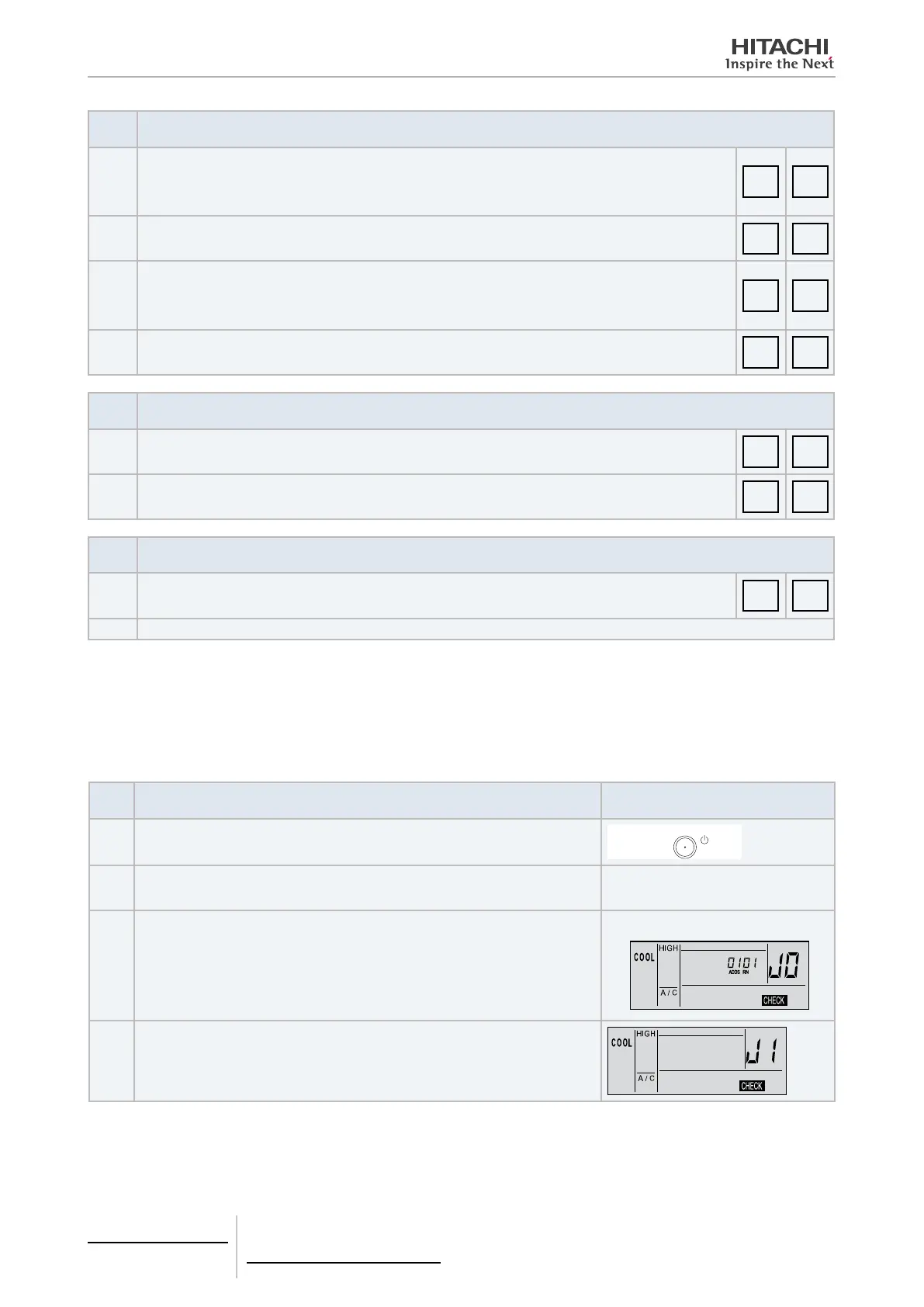
4.2.7.4 Checking procedure for each main component
PCB self-checking procedure using the remote control
Use the following troubleshooting procedure to check the PCB in both indoor and outdoor units.
Step
No.
Action required Image
1 Stop the machine by pressing the Run/Stop button.
Press
2
PCB check mode:
Press and hold both buttons for 3 seconds.
TEMP OK
5
3
Indication of the number of the outdoor unit (RN) and indoor unit (ADDS) to which
the remote control is connected.
e.g.: Indication of unit no. “01”
:
4
After 7 seconds:
Automatic PCB operation check.
(continued on next page)

 Loading...