8
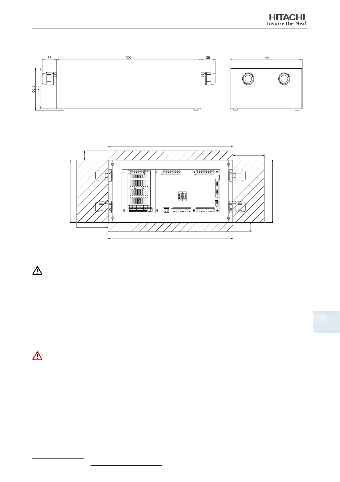
8.3.2.5 Dimensional data
(mm)
8.3.2.6 Installation space
Keep free grated area for ventilation and cable connection.
(mm)
300
70
70
20
20
140
8.3.2.7 Installation procedure
CAUTION
Before applying power and turning on PC-A1IO you must ensure that:
• All circuits to be connected are correctly applied.
• All H-Link connections have been set up.
• Follow the local regulations for the electrical installation of PC-A1IO and associated circuits.
Any unit that is not connected or is not under power when turning on PC-A1IO, will not be recognised and will have to be congured
later.
The signals’ cables should be as short as possible. Keep a distance of more than 150 mm from other power cables. Don’t wire them to-
gether (although they may intersect). If they must necessarily be installed together, take the following measures to avoid noise:
• Protect the signal cable with a metal tube which is earthed at one end.
• For communications, use shielded wire which is earthed at one end.
DANGER
• Always disconnect the power supply for PC-A1IO when handling the machine, in order to avoid eletrical discharges.
• Do not connect the interface to the power supply until the installation has been completed.
• Comply strictly with local security codes and regulations when connecting the machine to the electric network.
• You will need a three-wire cable (two cores and earth) with a suitable plug at one end.
Procedure
1 Remove the rubber supports
2 Unscrew the 4 screws from the top cover and remove it
3 Attach the box to the rear vertical board from the inside with M4 screws (not provided) and place 3 mm washers on the
outside to separate the box from the wall.
4 Reinstall the top cover. Be careful to position it correctly.
8 Control support devices
PC-A1IO
TCGB0106 rev.0 - 12/2014
721

 Loading...