4 Fix the switch box (Field-supplied: JIS Switch Box for 4
Switches (with cover) (JIS C8340) by accessory xing
screw (M4 x 16 mm).
M4 screws
(Q’ty: 4)
Switch box
(Field-supplied)
(JIS C8340 4 switches (with cover))
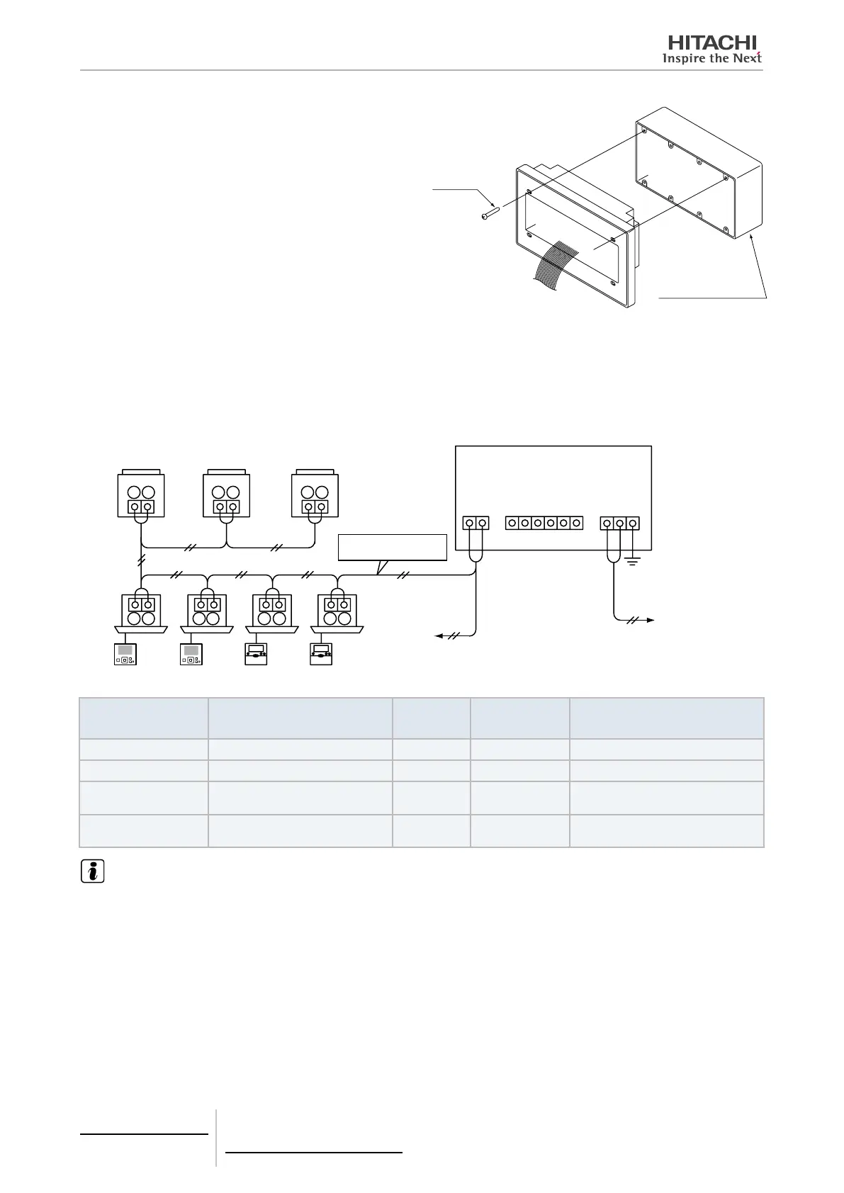
5.1.3 Electrical wiring
Electrical wiring connection
The central station requires wiring work for the power supply, air conditioner and control wiring (H-LINK) cables.
PSC-A64GT
1
123456
1
2
2
FG
1
1 1 1 1
1 1
2
2 2 2
2
2
2
Outdoor unit
Remote control switch
Indoor unit
To TB2
of central
station
Power supply
100 to 240V
Frame ground
terminal
Terminal
board TB2
Terminal
board TB3
Terminal
board TB1
H-LINK
(Transmission wire)
Connect the transmission
wires to the TB terminals
and of the outdoor
units and the indoor units.
Type of wiring Specication
Length of
wiring
Cable specica-
tion
Recommended cable model
Power supply cable AC100~240V
-
1.25 to 2.0 mm2 600V CV, CCV, CEV (Hitachi Cable)
Earth wiring
H-LINK (Control Wire) DC5V
≤1000m
0.75 to 1.25 mm2
Twist pair cable with shield > 0.75
mm2 (Equivalent to KPEV-S)
Wiring for external
input and output
Input: Non-voltage normal open
Output: DC12V, ≤75mA
≤70m
0.75 to 1.25 mm2
JKPEV-S, JKEV-S, CVV-S, CVV,
600V VCT (Hitachi Cable)
NOTE
• The central station may be damaged because of incorrect wiring.
• Transmission wires shall be separated from the power supply wiring and other electrical device wiring. Keep a separation of at least
30 cm between transmission wiring and the power supply wiring. If it is not possible to secure this space, then route the power supply
wiring and transmission wiring through separate metal conduit tubes. One end of the metal conduit tubes shall be earthed for noise
reduction.
• Do not connect the power supply wiring to the terminals for transmission of central station. However, if the power supply wires are
connected incorrectly, the fuse of the printed circuit board will blow out for protection. In such a case, turn ON pin 2 of DSW2 on the
printed circuit board to allow emergency operation without the fuse.
• Always remove the earth wiring of “FG” terminal when performing insulation capacity test or withstand voltage test. Failure to do so
may result in damage to the central station.
• Remove the earth wiring of “FG” terminal securely when the insulating capacity test or the withstand voltage test is performed. If the
above is not secured, it may cause of breaking down of the central station.
5 Centralised remote controls
PSC-A64GT
TCGB0106 rev.0 - 12/2014
224

 Loading...