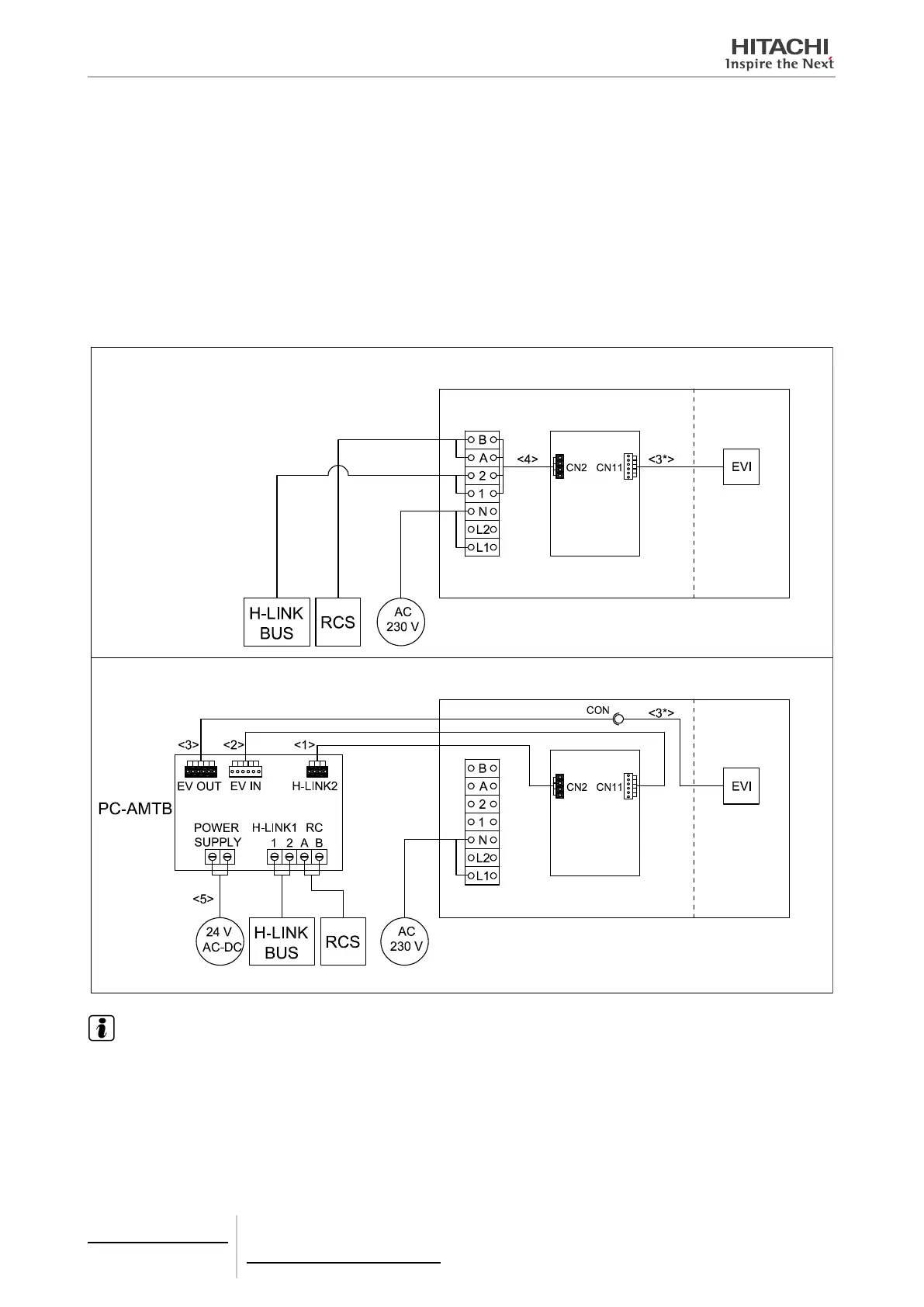
8.5.3.2 Electrical wiring
1
Make sure that indoor unit is switched off, and then, open the electrical box.
2
Disconnect the Remote Control (RCS) cable from the electrical box terminals of the indoor unit and connect it into the
PC-AMTB screw terminals “RC-A,B”.
3
Disconnect the H-LINK cable from the electrical box terminals of the indoor unit and connect it into the PC-AMTB
screw terminals “HLINK1-1,2”.
4
Remove wire <4> from IU electrical box (from terminal box and “CN2” connector).
5
Connect wire <1> from PC-AMTB ”HLINK 2” connector to IU PCB “CN2”.
6
Disconnect EVI wire <3*> from IU PCB “CN11” and switch it to connector wire <3>. The other ending of wire <3>
must be switched to PC-AMTB “EV OUT”.
7
Connect wire <2> between PC-AMTB “EV IN” and IU PCB “CN11”.
8
Connect power wires <5> to PC-AMTB screw terminals “POWER SUPPLY”.
INDOOR UNIT BEFORE PC-AMTB CONNECTION
INDOOR UNIT AFTER PC-AMTB CONNECTION
Indoor unit
PCB
Indoor unit
PCB
Indoor
unit
Indoor
unit
Indoor unit electrical box
Indoor unit electrical box
NOTE
• PCB: Printed circuit board.
• EVI: Indoor unit expansion valve.
• Connectors in wires named after connectors in PC-AMTB and IU PCB.
8 Control support devices
PC-AMTB
TCGB0106 rev.0 - 12/2014
740

 Loading...