: Main setting
: Setting before shipping
0 1 2 3 4 5 6 7
CAUTION
Do not set various main adapters in the same refrigerant cycle.
0
1
2
3
4
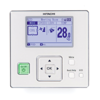
6 In case of wrongly applying high voltage to H-LINK wiring, fuse installed in a transmission circuit
on PCB is cut. In this case, after wiring correctly, turn ON No.2 pin of DSW4 on PCB and then
transmission circuit is recovered. (If you make this error again, the transmission circuit is not
recovered.)
PCB
DSW4
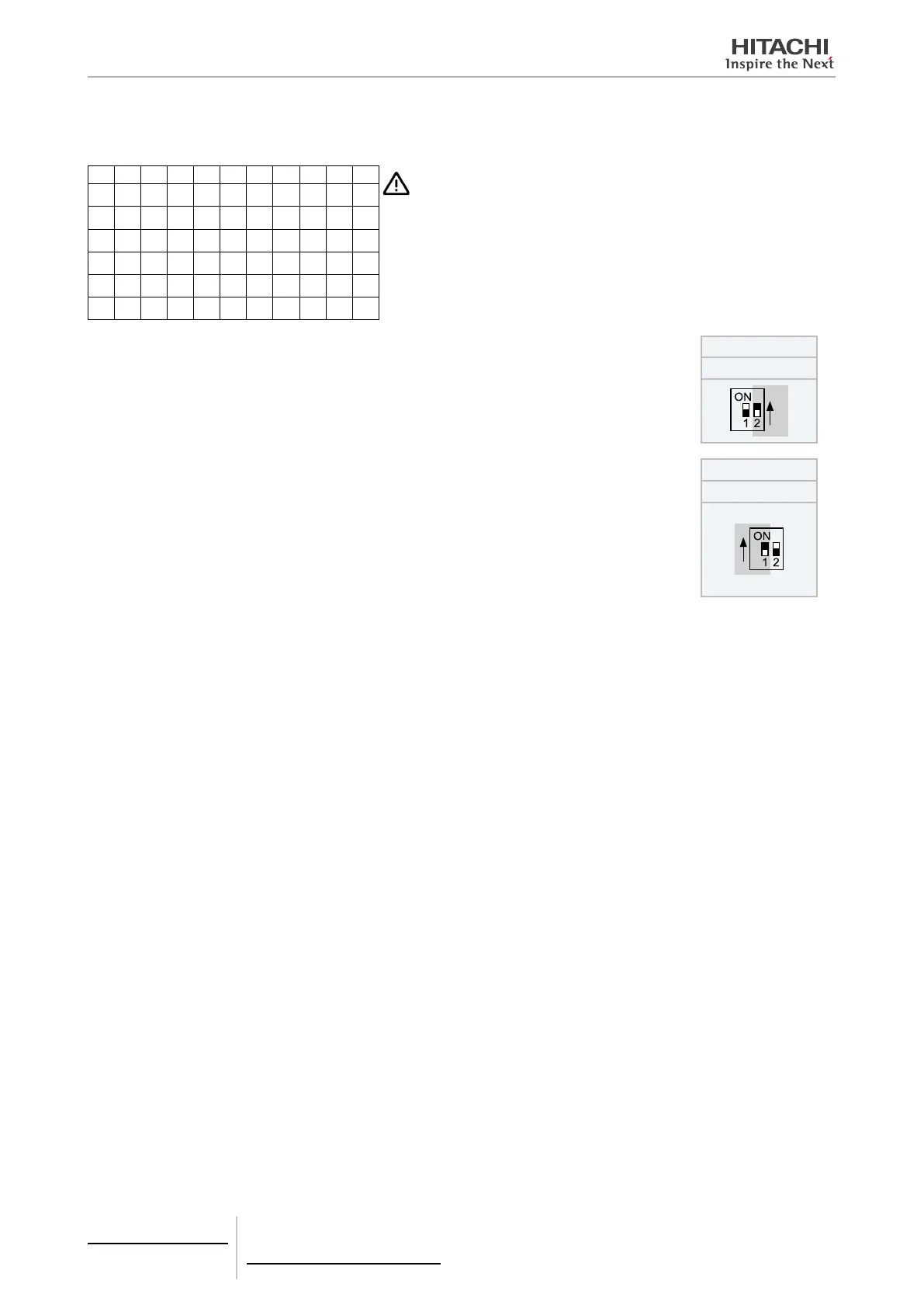
7 Terminal resistance is set in whole H-LINK.
a. If H-LINK connection devices like package air-conditioner is connected besides RAC adapt-
er, set the terminal resistance by package air-conditioner. The terminal resistance should be
ON in only one position in whole H-LINK.
b. In case that H-LINK is made up only by RAC adapter, set the terminal resistance by RAC
adapter. The terminal resistance should be ON in only one position in whole H-LINK.
PCB
DSW4
8.2.4 Test run
Test run should be performed in the following way after nishing the installation, wiring and setting.
See installation manual enclosed with each central control devices for the detail.
1 Connection State Conrmation
- Conrm if RAC adapter connection is recognised in the central control device. In case that it is not conrmed, check
the transmission cable, refrigerant cycle No. indoor unit No., terminal resistance setting etc.
2 Registration
- Conrm if RAC adapter connection is recognised.
3 Conrmation of Run/Stop Order
- Conrm if room air-conditioners work correctly by run/stop operation from the central control devices. Check also if
air-conditioner state changes correctly by each setting.
8 Control support devices
PSC-6RAD
TCGB0106 rev.0 - 12/2014
716

 Loading...