7.2.4 Operation
7.2.4.1 KNX Address
KNX Default address for this device is 1.1.1, it can later be modify using ETS software from KNX Association.
7.2.4.2 Available data
The maximum numbers of units that can be controlled using HC-A16KNX are 16. Each unit has 15 communication objects.
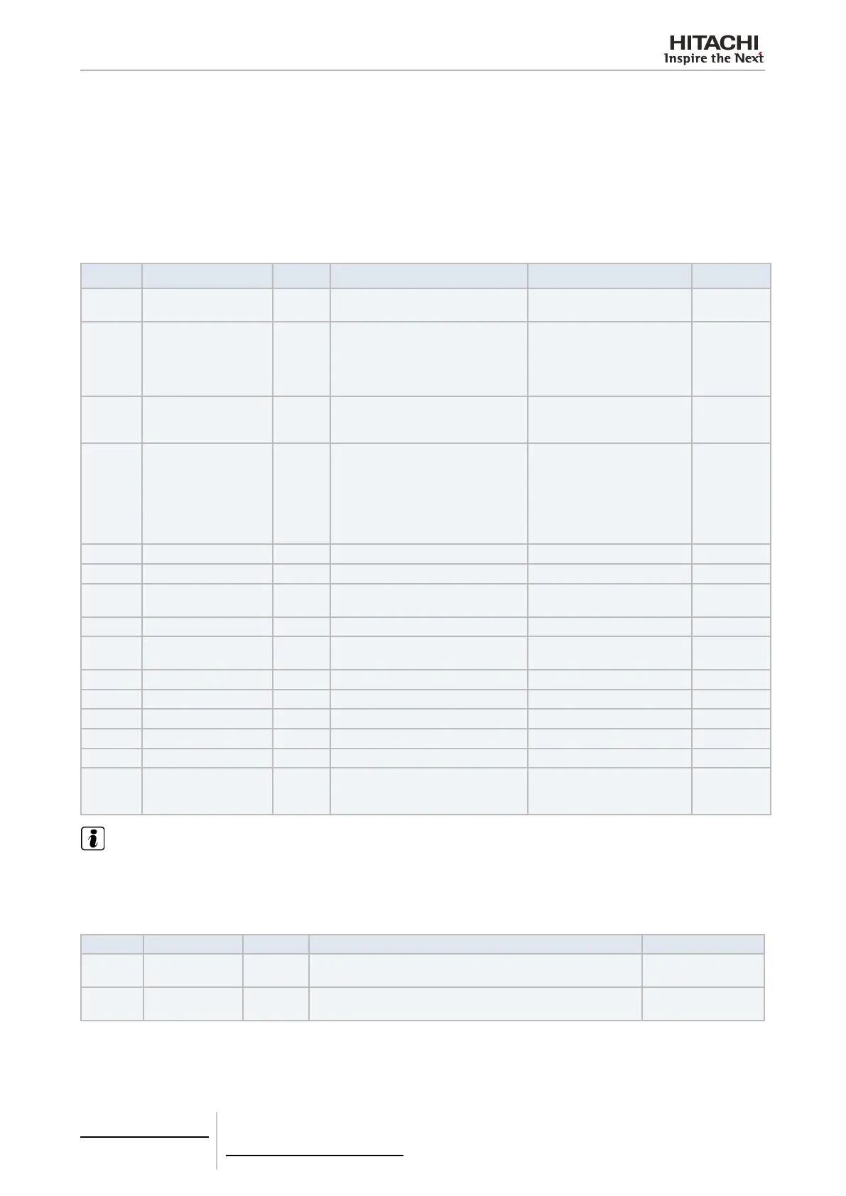
These objects are explained as follows:
Address Name Length Description Values Read/Write
0 Unit-N On/Off 1 bit ON / OFF order.
0-On
1-Off
Read/Write
1 Unit-N Mode 1 byte Mode setting order.
0 = Auto
1 = Heat
2 = Dry
3 = Fan
4 = Cool
Read
2 Unit-N Fan 1 byte Fan setting order.
0~30%= Low
31~60%= Medium
61~100%= High
Read/Write
3 Unit-N Louver Scale 1 byte Louver position setting.
0~15% = Pos0
16~30% = Pos1
31~45% =Pos2
46~60% = Pos3
61~75% =Pos4
76~90% = Pos5
91~100% = Pos6
Read/Write
4 Unit-N Louver Auto 1 bit Automatic Louver Setting. 1 = Louver Automatic active Read/Write
5 Unit-N Set Temperature 2 bytes Setting temperature. 17~30ºC Read/Write
6
Unit-N Ambient Tem-
perature
2 bytes Ambient Temperature. 17~30ºC Read
7 Unit-N Alarm 1 bit Alarm notication. 1 = alarm on unit N Read
8 Unit-N Alarm Code 1 byte Alarm code.
See errors table from
HC-A16KNX
Read
9 Unit-N Mode Cool 1 bit Cool mode order. 1 = Mode Cool Active Read/Write
10 Unit-N Mode Dry 1 bit Dry mode order. 1 = Mode Dry Active Read/Write
11 Unit-N Mode Fan 1 bit Fan mode order. 1 = Mode Fan Active Read/Write
12 Unit-N Mode Heat 1 bit Heat mode order. 1 = Mode Heat Active Read/Write
13 Unit-N Mode Auto 1 bit Auto mode order. 1 = Mode Auto Active Read/Write
14 Unit-N Prohibit 1 bit
On Yes works only with KNX orders,
on No, the unit could receive local
orders and from KNX too.
0 = No
1 = Yes
Read/Write
NOTE
Address from 9 to 13 will work together. They are used to set the function mode. Only one of them could be activated at the same time.
When one of these bits will be set as 1, the rest will be changed at 0.
Global objects:
Address Name Length Description Values
1~16 Unit-1~16
1 bit per
unit
Shows if HC-A16KNX used the communication with the H-LINK
PCB for unit N where N is the address to read.
1=Communication
works
240
Communication
Alarm
1 bit
With value is 1 means that is not possible to communicate with
the H-LINK PCB. On 0, communication is working properly.
1=Communication
Alarm.
7 Gateways for building management systems
HC-A16KNX
TCGB0106 rev.0 - 12/2014
642642

 Loading...