8
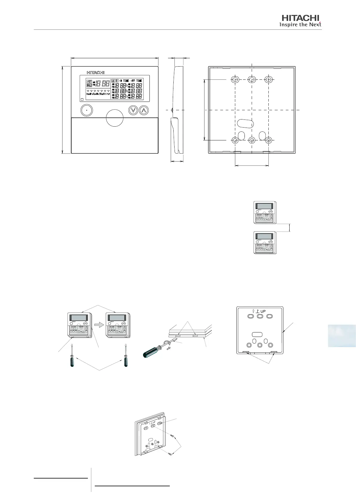
8.1.2.4 Dimensional data
(mm)
46
17
83.5
>ABS<
HOUR-MINUTE
SET/MONITOR
8.1.2.5 Installation space
If several control units are to be installed in a vertical position, leave a distance of at least
50 mm between them to allow the front cover to be opened and to insert the tool for remov-
ing the control from its housing.
At least
50 mm
8.1.2.6 Installation procedure
1 Using a at-head screwdriver, separate the control unit bracket from the front section, as indicated below:
Control timer
Bracket
Grove
Screwdriver
Grove
Bracket
Screwdriver
Bracket
Indent part
2 Secure the timer to the bracket and connect the cable as illustrated below.
In cases where the remote control cable is exposed.
1 Fix the bracket to the wall using the screws supplied
Attach the bracket with the
mark upwards
Screws (accessories)
8 Control support devices
PSC-A1T
TCGB0106 rev.0 - 12/2014
697

 Loading...