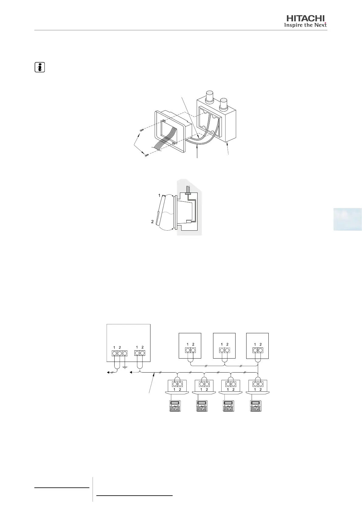
2 Connect the power supply part to the control box, as shown below.
NOTE
Do not lay the cables from the power source and the control unit in the same duct, since the power cable is liable to cause interference
with the control cable.
Control cable
Screws
Power supply part
Power supply wire
Control box
3 Connect the control unit part to the power supply part. Join them at the top rst, then at the bottom.
5.3.3 Electrical wiring
Electrical wiring connection
Up to 8 central controls can be connected to the H-LINK system.
Use the 2-core cable of 0.75-1.25 mm
2
or the 2-core twist pair cable (Max. 1.000 m) for the transmission cable for the
central station, for the outdoor unit and between indoor units (DC5V). The maximum total length of the cables shall be
within 1.000 m.
To connect to terminal block 1 and 2 of the indoor unit
and the outdoor unit
Outdoor units
Indoor units
Remote
control switch
Shielded twisted pair cable
(1p-0.75 mm2) or Twisted
pair cable
Power source
(220VAC or 240 VAC)
To TB2 of other
central stations
Central station
Terminal
board 1
Terminal
board 2
H-LINK
(control line)
5 Centralised remote controls
PSC-A64S
TCGB0106 rev.0 - 12/2014
373
5

 Loading...