8.1.3 Electrical wiring
8.1.3.1 Electrical connection of PSC-A1T timer combined with individual or central controllers
This section explains how to electrically connect the timer to another remote controls or central stations.
CAUTION
Use a twisted pair cable (1P - 0.75 mm
2
) as a transmission cable to avoid possible communication errors. If the cable exceeds 30 m in
length, use:
• Shielded pair cable (connected to earth protection on one side).
• Normal pair cable.
The transmission cable and the remote control cable must be kept at least 30 cm apart.
When installing the timer on an RPK unit, rst disable the wireless remote control and then connect a different remote control. The timer
can then be connected to the other remote.
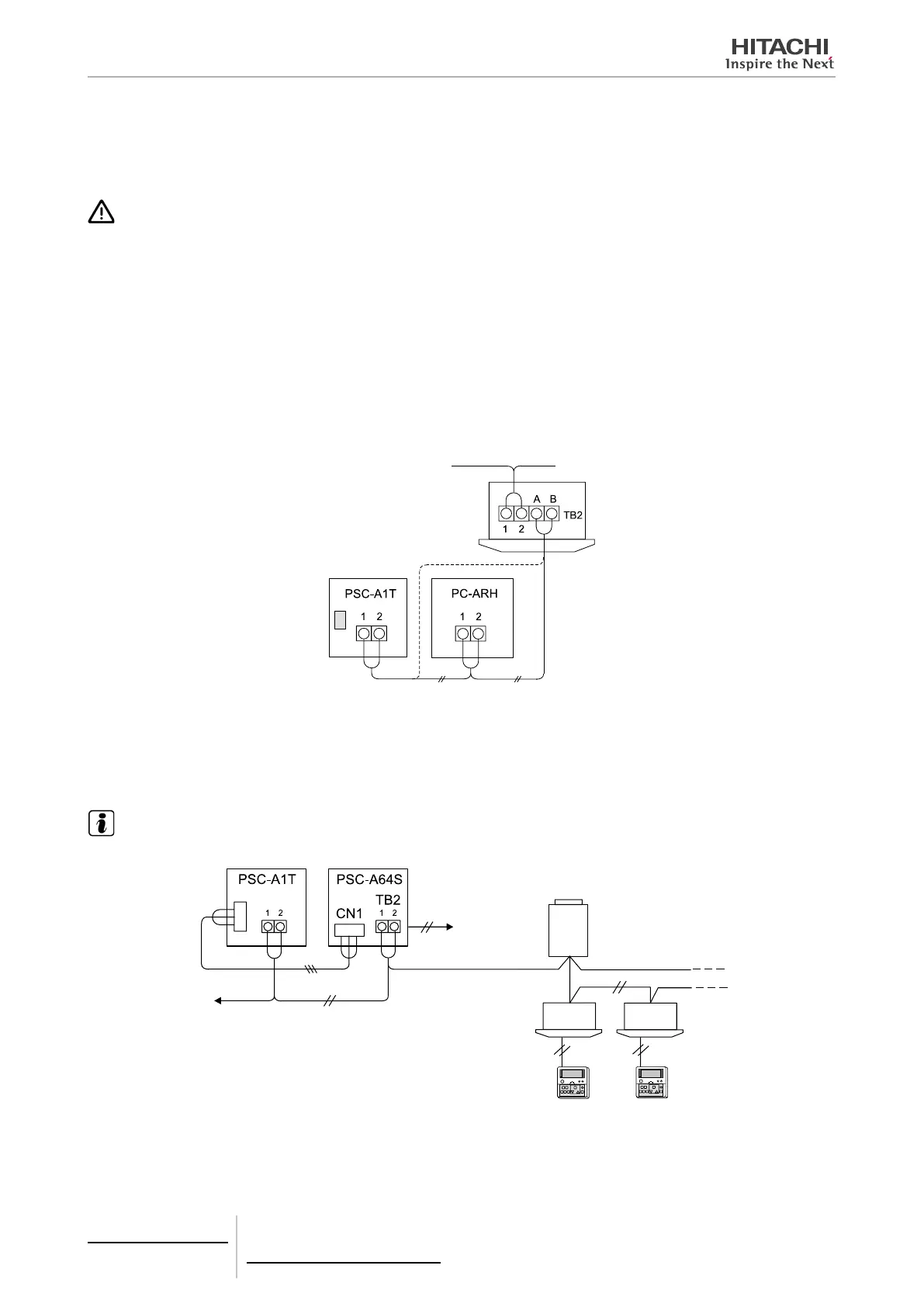
PSC-A1T timer combined with PC-ARH or wireless remote control receivers
Set DSW1-4 pin and DSW2-2 pin to ON position on the PSC-A1T.
Transmission cable be-
tween the indoor and
outdoor units (H-LINK)
Twisted pair cable 1P - 0.75 mm²
(max. 100 m) eld supplied
Indoor unit
PSC-A1T timer combined with PSC-A64S central control
Set DSW1-4 and DSW2-2 pins to OFF position on the PSC-A1T.
NOTE
Up to 8 PSC-A64S central control units and one PSC-A1T timer can be connected to one H-Link.
Connector
220 VAC or 240 V
power supply
Outdoor unit
Indoor units
Remote control
switch
Available for H-Link connec-
tion (to connect to the indoor
or to the outdoor unit termi-
nal boards 1 and 2)
Twisted pair cable
1P - 0.75 mm²
(max. 1000 m)
To TB2 of other cen-
tral stations
Accessory cable (1 m)
8 Control support devices
PSC-A1T
TCGB0106 rev.0 - 12/2014
700

 Loading...