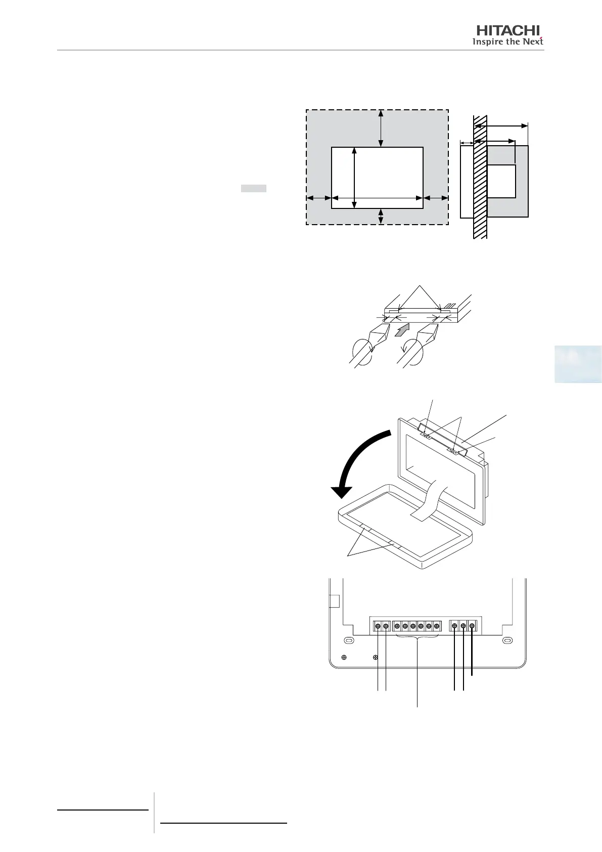
5.1.2.6 Installation space
Keep the installation space for the central station as shown
in the gure.
When installing more than 2 central stations in row or in
line, keep the space between each.
* Vertical Direction: 100 mm
* Horizontal Direction: 50 mm
Do not attach anything in the halftone screen area “ ”.
100
250
170
50
30
50
25
55
70
(Unit: mm)
5.1.2.7 Installation procedure
1 Install the switch box into the wall. (Field-supplied: JIS
Switch Box for 4 Switches (with cover) (JIS C8340).
2 Open the unit body. (The unit body is opened when the
factory shipping). If the unit body is closed, open it as
shown below.
a. Open the top cover of unit body.
b. While pressing the convex part (2 portions), pull the
top case and it is opened because the catches for x-
ing are removed.
Front case
Approx. 6 mm
Slotted screw driver
View from lower side
Catch for xing
Convex part
Top
cover
Catch
for
xing
Hook
3 Connect the wiring to the terminal board of the central
station.
TB1: Terminal Board for Power Supply
TB2: Terminal Board for H-LINK
TB3: Terminal Board for External Input and Output
TB2 TB3 TB1
FG
H-LINK (Non-pole)
Terminals for external input/output
Refer to item External input/output setting
AC100 to 240V
5 Centralised remote controls
PSC-A64GT
TCGB0106 rev.0 - 12/2014
223
5

 Loading...