5.4.3 Electrical wiring
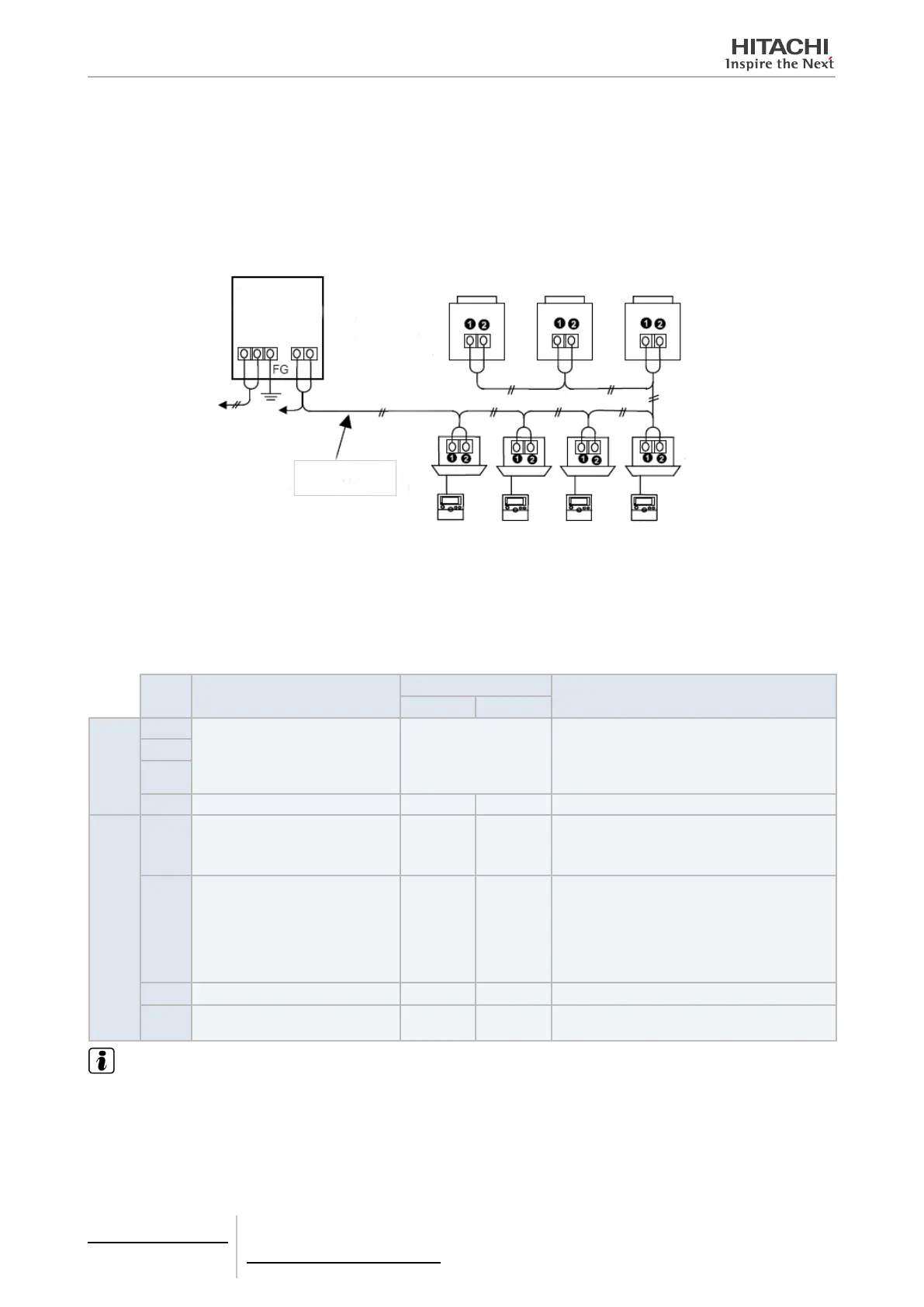
Electrical wiring connection
Up to 8 centralised ON/OFF controllers can be connected to the H-LINK II (Control Line).
Use the 2-core cable of 0.75-1.25 mm
2
or the 2-core twist pair cable (Max. 1,000 m) for the transmission cable for the
centralised ON/OFF controller, for the outdoor unit and between indoor units (DC5V). The maximum total length of the
cables shall be within 1,000m.
H-LINK II (Control line)
Twist pair cable with
shield 0.75 mm
2
To be connected to the
terminal board and of
indoor unit or outdoor unit
Outdoor unit
Indoor unit
Remote Control Switch
To TB2 of Centralised
ON/OFF Controller
Power Supply
(AC 220V or 240V)
DIP switch setting
Set the dip switches as shown below.
The address setting is required only if multiple centralised ON/OFF controllers (Max. 8 units) are connected to the H-
LINK(Control Line). (The setting of dip switches is all OFF before shipping).
Pin
No.
Contents
Setting of DSW
Remarks
OFF ON
SW18
1
For Address Setting Refer to the SW18 table.
For connecting plural centralised ON/OFF con-
trollers with H-LINK (control line), the address
setting for each centralised ON/OFF controllers is
required. (*)
2
3
4 Not In Use - - Set SW18-4 pin OFF.
SW19
1
External Input 1 Function
Changeover Operation Stoppage
Level / Pulse
Level Pulse
Available only when the SW19-1 pin is OFF.
Pulse Stop when the SW19-1 pin is ON.
2
Simultaneous Use of Other
Centralised Controller
No Yes
When using the following centralised controllers
simultaneously, set the SW19-2 pin ON.
Central Station III-S
Central Station W
Central Station Web
3 Not In Use - - Set SW19-3 pin OFF.
4 H-LINKII Adaptive Adaptive
Non-Adap-
tive
Set SW19-4 pin OFF: H-LINK II adaptive.
Set SW19-4 pin ON: Non-H-LINK II adaptive.
NOTE
(*): When using the multiple centralised ON/OFF controllers in the same H-LINK (control line) system, set the SW18 not to be overlapped.
5 Centralised remote controls
PSC-A16RS
TCGB0106 rev.0 - 12/2014
398

 Loading...