FUEL SYSTEM (Programmed Fuel Injection)
6-7
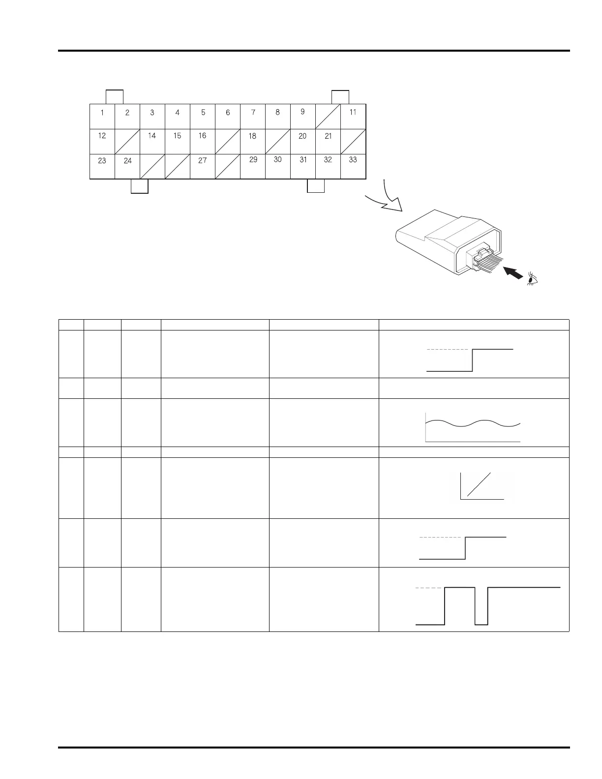
ECM TERMINAL ARRANGEMENT
IGP
PCP
PCM TW
PB PCV
TA SCS INJ WARN
STSW
LG O2 SG THL VCC FLR PG IGPLS
IACV2A
IACV2B IACV1B
IACV1A
ST-MAG
K-LINE
IG-ON: Ignition switch ON
IG-OFF: Ignition switch OFF
COLOR
NAME
FUNCTION DESCRIPTION SIGNAL
1 Bl/W IGP INPUT-ECM POWER ECM control circuit
input power line
2 G LG LOGIC GND ECM control circuit
ground line
–
3 Bl/O O
2 INPUT-O2 SENSOR O2 SENSOR input sig-
nal
4 G/O SG SENSOR GND sensor ground line –
5 W/R THL INPUT-TP SENSOR TP sensor input signal
6 Y/O VCC OUTPUT-5V POWER output power line for
sensors
7 Br/Bl FLR DRIVER FUEL PUMP
RELAY
fuel pump relay coil
drive signal
Full
close
Full
open
4.76 V
0.29 V
0 V
12 V
IG-
ON
2 sec.
Engine start
IG-
OFF
 Loading...