IGNITION SYSTEM
19-7
Remove the luggage box (page 3-8).
Turn the ignition switch OFF.
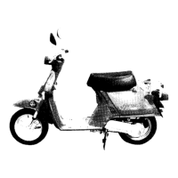
Disconnect the CKP sensor 2P connector and con-
nect the imrie diagnostic tester or peak voltage
adaptor probes to the connector terminals of the
CKP sensor side.
Turn the ignition switch ON and squeeze the brake
lever fully.
Crank the engine with the starter motor and mea-
sure the CKP sensor peak voltage.
In the same manner as at the ECM 33P connector,
measure the peak voltage and compare it to the
voltage measured at the ECM 33P connector.
• If the peak voltage measured at the test harness
is abnormal and the one measured at the CKP
sensor is normal, the wire harness has an open
or short circuit, or loose connection.
• If both peak voltages are abnormal, check each
item in the troubleshooting chart (page 19-4).
For CKP sensor replacement (page 13-4).
IGNITION COIL
REMOVAL/INSTALLATION
Remove the body cover (page 3-9).
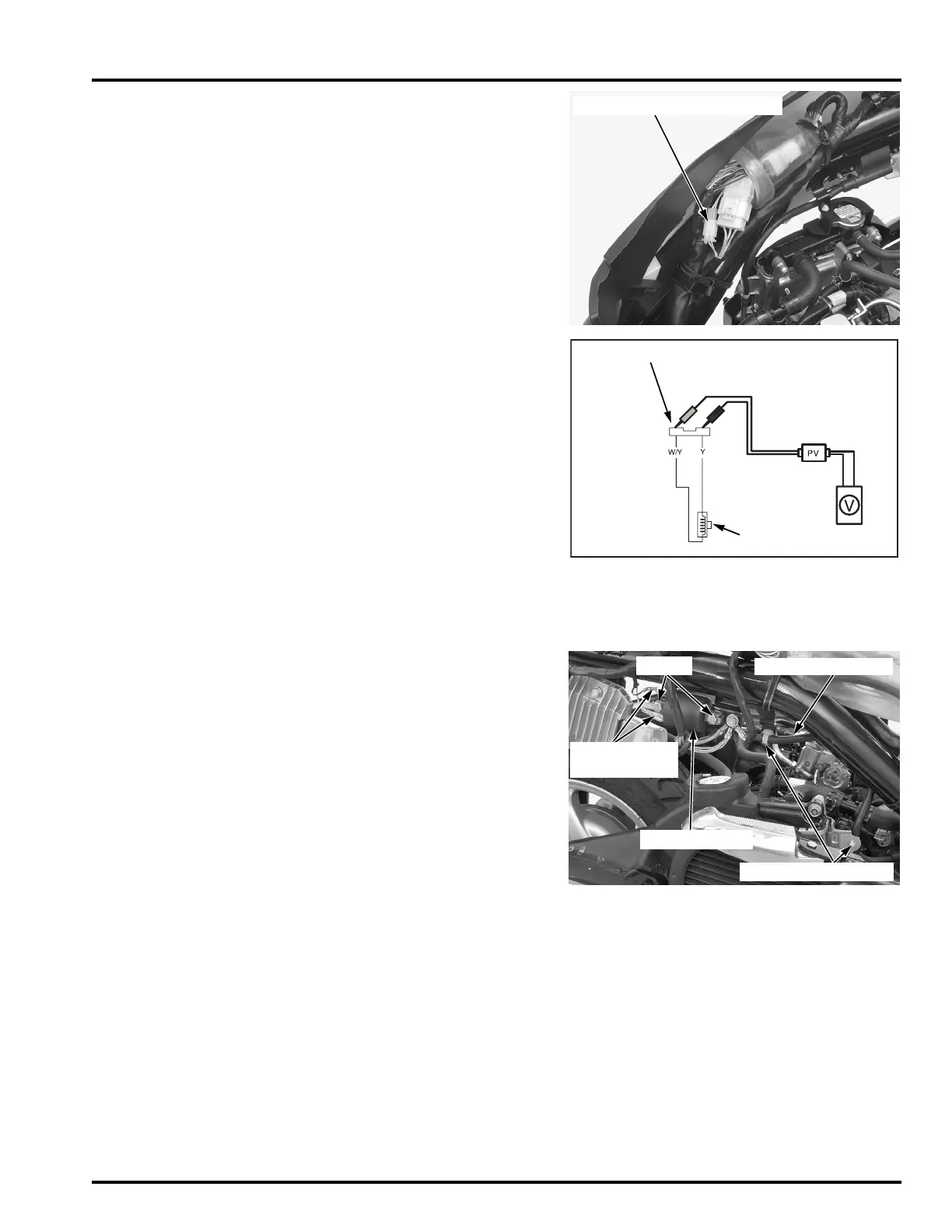
Disconnect the spark plug cap.
Release the wire band bosses from the frame stay
and radiator base.
Disconnect the ignition coil primary wire connec-
tors.
Remove the mount bolts and ignition coil.
Installation is in the reverse order of removal.
TOOL:
Imrie diagnostic tester (model 625) or
Peak voltage adaptor 07HGJ-0020100
with commercially available digital multimeter
(impedance 10 MΩ/DCV minimum)
CONNECTION: White/Yellow (+) – Yellow (–)
PEAK VOLTAGE: 0.7 V minimum
CKP SENSOR 2P CONNECTOR
CKP SENSOR
CKP SENSOR 2P CONNECTOR
(+)
(–)
Route the wire har-
ness properly (page
1-17).
SPARK PLUG WIRE
BOLTS
WIRE BAND BOSSES
IGNITION COIL
WIRE
CONNECTORS
 Loading...