BATTERY/CHARGING SYSTEM
18-6
BATTERY
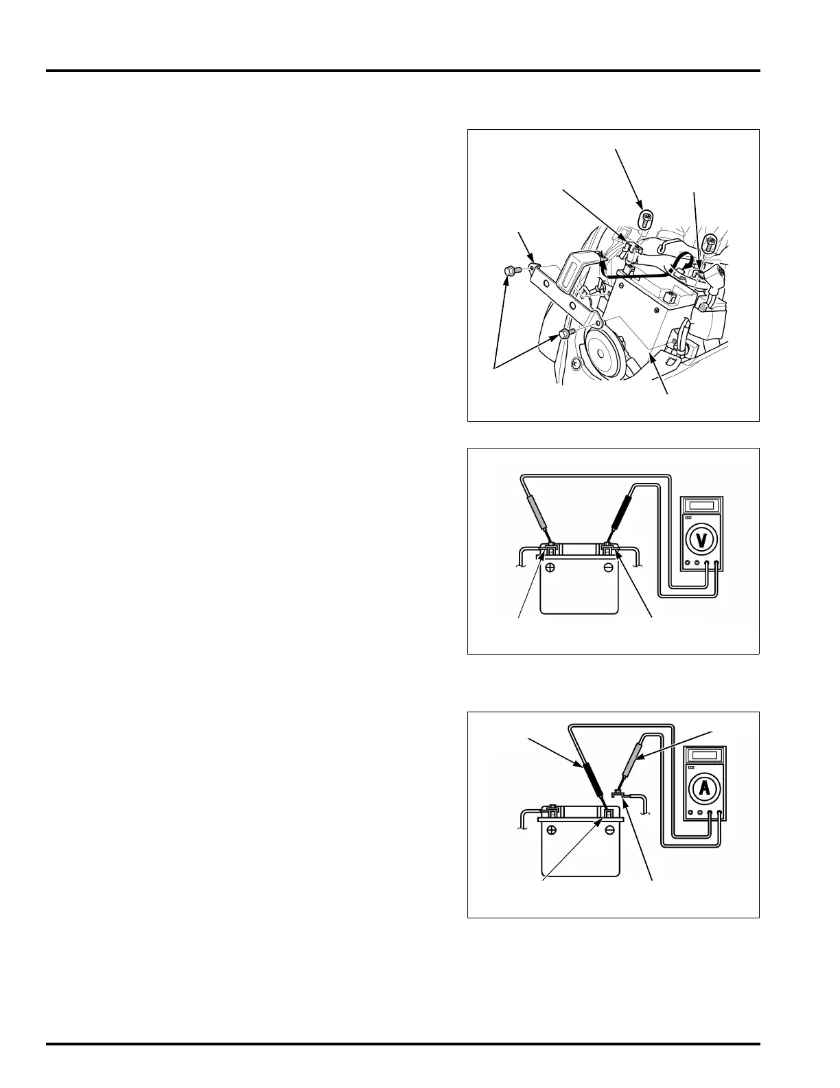
REMOVAL/INSTALLATION
Remove the front center cover (page 3-4).
Remove the bolt and disconnect the negative (–)
cable.
Remove the bolt and disconnect the positive (+)
cable.
Remove the bolts and unhook the battery holder.
Remove the battery.
Install the battery in the reverse order of removal.
Install the front center cover (page 3-4).
VOLTAGE INSPECTION
Remove the front center cover (page 3-4).
Measure the battery voltage using a digital
multimeter.
If the battery voltage is below 12.3 V, charge the bat-
tery.
CHARGING SYSTEM INSPECTION
CURRENT LEAKAGE INSPECTION
Remove the front center cover (page 3-4).
Turn the ignition switch OFF and disconnect the
negative (–) cable from the battery.
Connect the ammeter (+) probe to the battery (–)
cable and the ammeter (–) probe to the battery (–)
terminal.
With the ignition switch OFF, check for current leak-
age.
• When measuring current using a tester, set it to a
high range, and then bring the range down to an
appropriate level. Current flow higher than the
range selected may blow the fuse in the tester.
• While measuring current, do not turn the ignition
switch ON. A sudden surge of current may blow
the fuse in the tester.
If current leakage exceeds the specified value, a
shorted circuit is likely.
Locate the short by disconnecting connections one
by one and measuring the current.
Always turn the
ignition switch OFF
before removing
the battery.
Disconnect the
negative terminal
first, then the posi-
tive terminal.
Connect the posi-
tive terminal first,
then the negative
terminal.
NEGATIVE (–)
TERMINAL
POSITIVE (+)
TERMINAL
BOLTS
BATTERY
HOLDER
BATTERY
TERMINAL BOLTS
VOLTAGE:
Fully charged: Above 12.8 V
Needs charging: Below 12.3 V
NEGATIVE (–)
TERMINAL
POSITIVE (+)
TERMINAL
SPECIFIED CURRENT LEAKAGE: 0.1 mA max.
NEGATIVE (–)
TERMINAL
NEGATIVE (–)
CABLE
(+) PROBE
(–) PROBE
 Loading...