FUEL SYSTEM (Programmed Fuel Injection)
6-22
MIL TROUBLESHOOTING
MIL 1 BLINK (MAP SENSOR)
1. Recheck MIL Blinks
Erase the self diagnosis memory data from the
ECM (page 6-15).
Turn the ignition switch "ON".
Check the MIL blinks.
How many times does MIL blink?
1 and 8 or 1,8,9 all blinks –
GO TO SENSOR UNIT
POWER/GROUND CIRCUIT INSPECTION
(page 6-21)
.
1 blink – GO TO STEP 2.
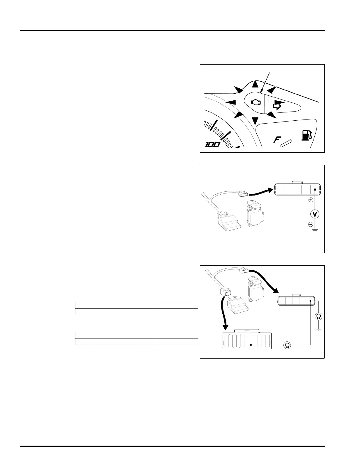
2. MAP Sensor Input Voltage Inspection
Turn the ignition switch "OFF".
Disconnect the sensor unit 5P connector.
Turn the ignition switch "ON".
Measure the voltage between the sensor unit 5P
connector of the wire harness side and ground.
Is the voltage within 3.8 – 5.25 V?
YES – Replace the sensor unit with a new one,
and recheck. (Faulty MAP sensor)
NO – GO TO STEP 3.
3. MAP Sensor Circuit Continuity Inspection
Turn the ignition switch "OFF".
Disconnect the ECM 33P connector.
Check for continuity between the sensor unit 5P
connector and the ECM 33P connector of the
wire harness side.
Check the continuity between the sensor unit 5P
connector of the wire harness side and ground.
Are the above inspections normal?
YES – Replace the ECM with a new one, and
recheck.
NO – • Open circuit in Yellow/Red wire.
• Short circuit in Yellow/Red wire.
CONNECTION: Yellow/Red (+) – Ground (–)
STANDARD: 3.8 – 5.25 V
ECM
SENSOR
UNIT
5P CONNECTOR
CONNECTION STANDARD
Yellow/Red – Yellow/Red Continuity
CONNECTION STANDARD
Ye l l o w / R e d – Ground No continuity
ECM
SENSOR
UNIT
33P CONNECTOR
5P CONNECTOR
 Loading...