For
HP
Internal Use
Only
The
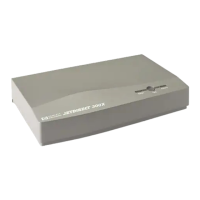
switchbox performs a function similar
to
that
of
the
Access
Port
"Enable Remote"
command.
If
the
switchbox is set
to
position
"A",
a session
through
the
modem is created
through
port
2 on
the
local system. This is
the
normal "session access"
to
the
system for Response Center
personnel
and
end-users for remote system administration.
If
the
switch box is set
to
position
"B",
access
through
the
modem is
to
port
7 on
the
local
system.
The
local system
must
be configured with
the
remote console
permanently
enabled
(AP
ER
command). This setup allows access
to
the
console
port
and
is considered
the
"remote console" connection
that
is traditionally provided by
the
Access
Port.
Note
that
the
local console
port
is left open for local console usage as needed. Onsite
support
by authorized service providers may be performed
through
the
attachment
of a terminal
device
to
port
0.
Hewlett-Packard Customer Engineers
(CEs)
in
Japan
use
the
HP
Omnibook 300
PC
with
an
HP
terminal
emulator
and
a 9-pin
to
25-pin serial cable as a "service console". Users of this
and
other
terminal
emulation devices should set
the
device
to
9600
baud,
8
data
bits, 1 stop
bit,
and no parity. Omnibook users should select
"COMM
1",
and
use a 24542M
or
similar
9-
pin
to
25-
pin serial cable for connection
to
port
0.
Memory
Subsystem
Configuration
The
memory subsystem consists Single In-line Memory Modules (SIMMs)
that
plug
into
the
CPU
card assembly.
Note
HP
9000/800 Ex5 Class memory SIMMs are
not
interchangeable (or
compatible) with any
HP
9000/800
F,
G, H,
or
I Class memory SIMMs.
Also,
HP
3000/9X8LX/RX
memory SIMMs are
not
interchangeable (or
compatible) with
HP
3000/9X7LX/RX/SX
memory SIMMs.
Figure 4-8 shows
the
memory SIMM card slot numbering scheme. Notice
that
there are four
slots, numbered
0
to
3 right
to
left, with two connectors per slot (A
and
B). These memory
slots are located on
the
CPU
card
near
the
card bulkhead.
4-14 Configuration
 Loading...


