p d t
ro
uc
F t
·ac
ory
nUlllber
Integrated
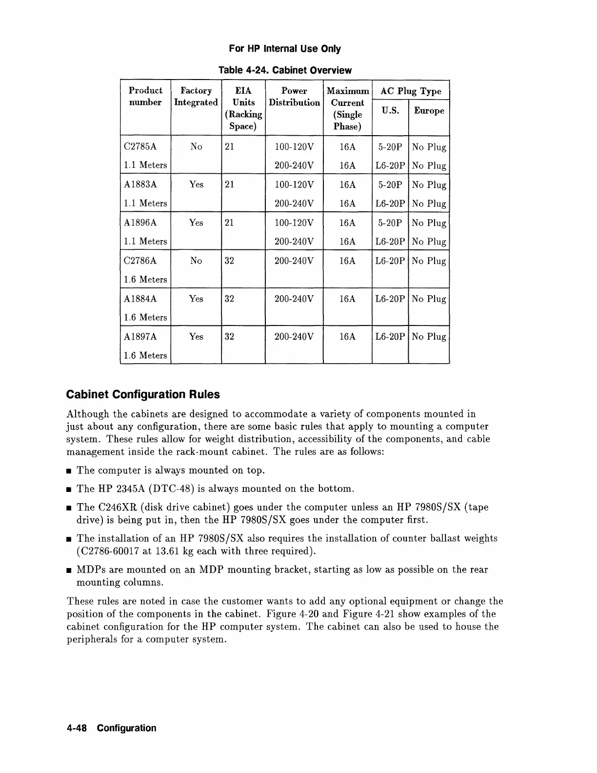
C2785A
No
1.1 Meters
A1883A Yes
1.1 Meters
A1896A
Yes
1.1 Meters
C2786A No
1.6 Meters
A1884A Yes
1.6 Meters
A1897A
Yes
1.6 Meters
For
HP
Internal Use Only
Table
4-24. Cabinet Overview
I
EI'
.tl.
p
ower
I
"'!:v,..
•
llaxlinUlll
Units
Distribution
Current
(Racking
(Single
Space)
Phase)
21
100-120V
16A
200-240V
16A
21
100-120V
16A
200-240V
16A
21
100-120V
16A
200-240V 16A
32
200-240V
16A
32
200-240V 16A
32
200-240V
16A
Cabinet Configuration Rules
AC
PI T
ug
·
ype
u.s.
Europe
5-20P
No
Plug
L6-20P No
Plug
5-20P
No
Plug
L6-20P
No
Plug
5-20P No
Plug
L6-20P No
Plug
L6-20P No
Plug
L6-20P No
Plug
L6-20P No
Plug
Although
the
cabinets are designed
to
accommodate a variety
of
components mounted in
just
about
any configuration, there are some basic rules
that
apply
to
mounting a computer
system. These rules allow for weight distribution, accessibility of
the
components,
and
cable
management
inside
the
rack-mount cabinet.
The
rules are as follows:
•
The
computer is always
mounted
on top.
•
The
HP
2345A (DTC-48) is always mounted on
the
bottom.
•
The
C246XR (disk drive cabinet) goes under
the
computer unless
an
HP
79808
/8X
(tape
drive) is being
put
in,
then
the
HP
79808/8X
goes under
the
computer first.
•
The
installation
of
an
HP
79808
/8X
also requires
the
installation of counter ballast weights
(
C2786-60017
at
13.61 kg each with three required).
•
MDPs
are mounted on
an
MDP
mounting bracket,
starting
as low as possible on
the
rear
mounting
columns.
These rules are noted in case
the
customer wants
to
add any optional equipment
or
change
the
position
of
the
components in
the
cabinet. Figure 4-20
and
Figure 4-21 show examples
of
the
cabinet configuration for
the
HP
computer system.
The
cabinet can also be used
to
house
the
peripherals for a computer system.
4-48 Configuration
 Loading...