0
<(
w
I
~
_j
:::>
co
0
cr:
<(
(_)
:::>
0...
(_)
For
HP
Internal Use Only
nn
nn
nn
nn
T I 11111111
Ill'
I
II
Ill I I
II
II
II~
11111111111
i
~
~u
~~
Ul
B A B A B A
B A
SLOT
SLOT
SLOT
SLOT
3
2 1
0
I
cr:
0
0
w
z
z
0
0
w
z
<(
_j
ug
L____
____
l
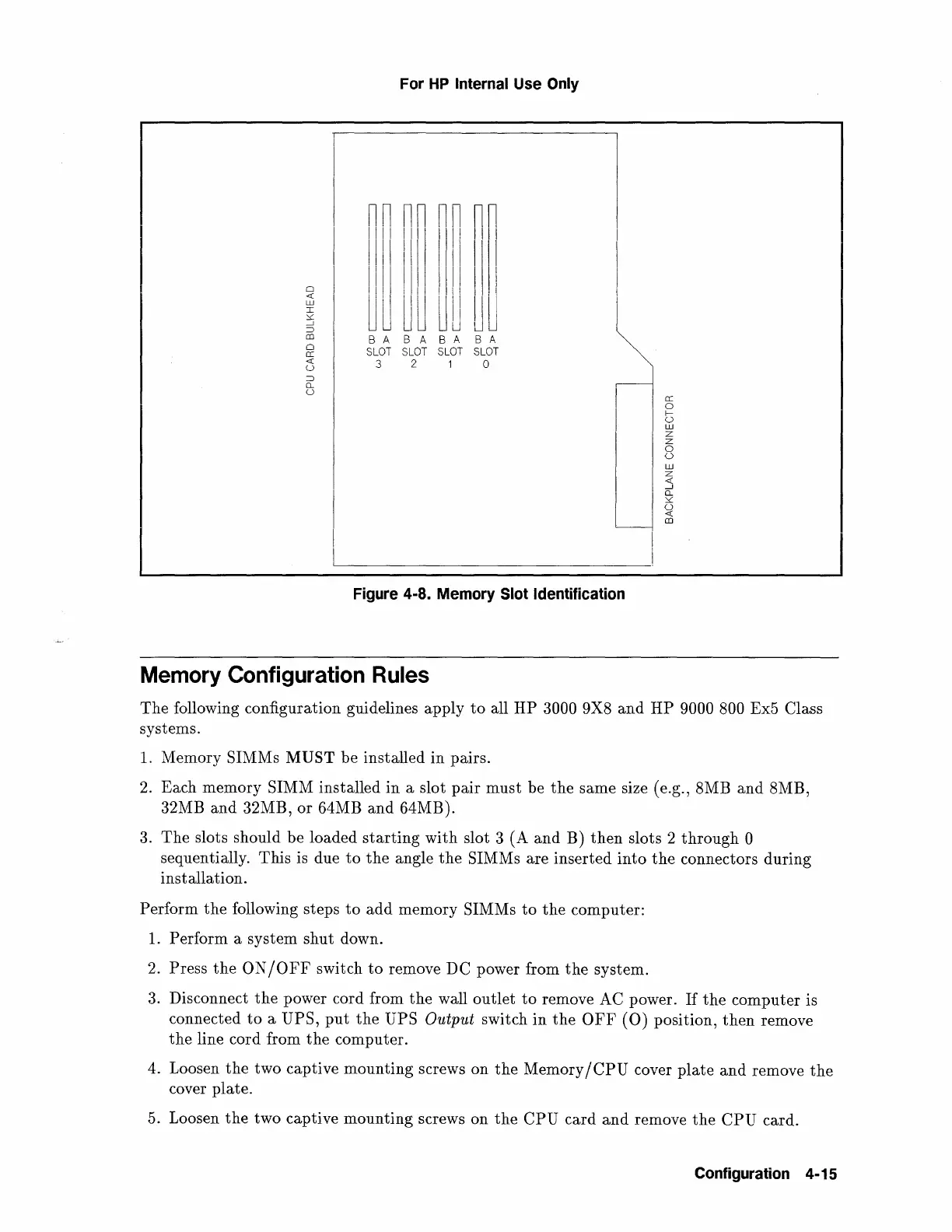
Figure 4-8. Memory Slot Identification
Memory
Configuration
Rules
The following configuration guidelines apply
to
all HP 3000 9X8
and
HP 9000 800 Ex5 Class
systems.
1.
Memory SIMMs MUST be installed in pairs.
2.
Each memory SIMM installed
in
a slot pair must be
the
same size (e.g., 8MB and 8MB,
32MB and 32MB, or 64MB and 64MB).
3.
The slots should be loaded
starting
with slot 3 (A
and
B)
then
slots 2 through 0
sequentially. This is due
to
the
angle
the
SIMMs are inserted
into
the
connectors during
installation.
Perform the following steps
to
add memory SIMMs
to
the
computer:
1.
Perform a system shut down.
2.
Press
the
ON
/OFF
switch
to
remove DC power from
the
system.
3.
Disconnect
the
power cord from
the
wall outlet
to
remove AC power.
If
the
computer is
connected
to
a UPS,
put
the
UPS Output switch
in
the
OFF
(0)
position,
then
remove
the line cord from
the
computer.
4. Loosen
the
two captive mounting screws on
the
Memory
/CPU
cover
plate
and remove
the
cover plate.
5.
Loosen
the
two captive mounting screws on
the
CPU card
and
remove
the
CPU
card.
Configuration 4-15
 Loading...