l Run the reset gtsm statistics all command in the user view to clear the GTSM statistics
on the board.
----End
4.14 Configuration Examples
This section provides several configuration examples of OSPF.
4.14.1 Example for Configuring Basic OSPF Functions
Networking Requirements
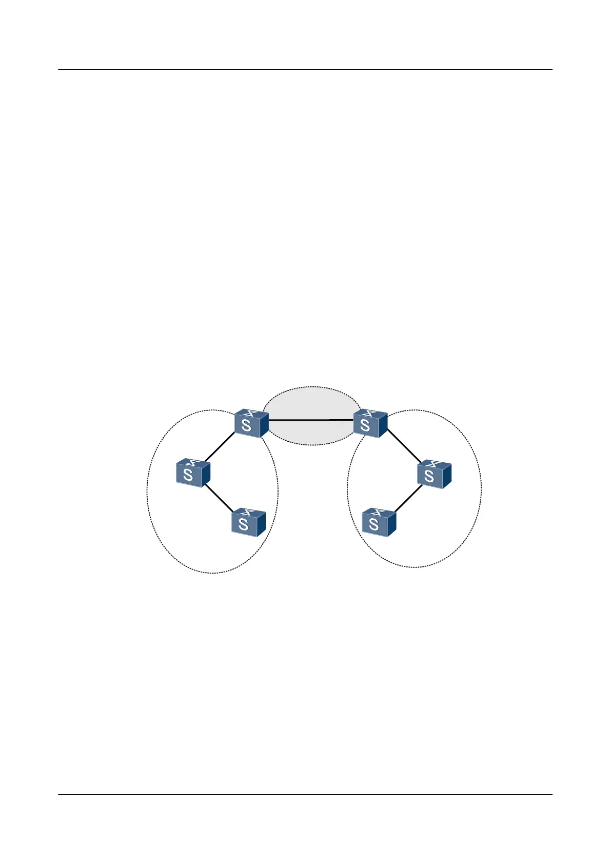
As shown in Figure 4-5, all switches run OSPF, and the entire AS is partitioned into three areas.
Switch A and Switch B serve as ABRs to forward routes between areas.
After the configuration, each Switch should learn the routes to all network segments from the
AS.
Figure 4-5 Networking diagram of basic OSPF configurations
Switch A
Switch C
Switch D
Switch E
Switch F
Area 0
Area 1
Area 2
XGE 0/0/1
XGE 0/0/1
XGE 0/0/1
XGE 0/0/1
XGE 0/0/1
XGE 0/0/1
XGE 0/0/2
XGE 0/0/2
XGE 0/0/2
XGE 0/0/2
Switch B
Switch
Interface VLANIF Interface IP Address
Switch A XGE0/0/1 VLANIF 10 192.168.0.1/24
Switch A XGE 0/0/2 VLANIF 20 192.168.1.1/24
Switch B XGE 0/0/1 VLANIF 10 192.168.0.2/24
Switch B XGE 0/0/2 VLANIF 30 192.168.2.1/24
Switch C XGE 0/0/1 VLANIF 20 192.168.1.2/24
Switch C XGE 0/0/2 VLANIF 40 172.16.1.1/24
Switch D XGE 0/0/1 VLANIF 30 192.168.2.2/24
Switch D XGE 0/0/2 VLANIF 50 172.17.1.1/24
Switch E XGE 0/0/1 VLANIF 40 172.16.1.2/24
S6700 Series Ethernet Switches
Configuration Guide - IP Routing 4 OSPF Configuration
Issue 01 (2012-03-15) Huawei Proprietary and Confidential
Copyright © Huawei Technologies Co., Ltd.
136

 Loading...