1.6.3 Example for Configuring BFD for IPv4 Static Routes
Networking Requirements
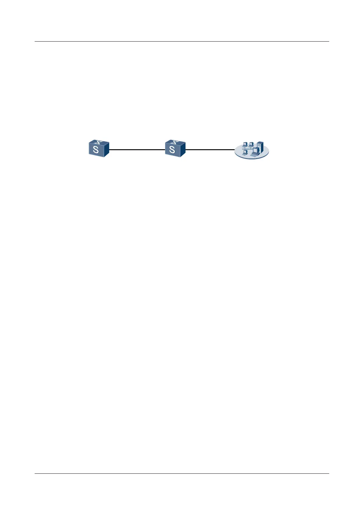
As shown in Figure 1-3, Switch A is connected to the network management system (NMS)
through Switch B. You need to configure static routes on Switch A so that Switch A can
communicate with the NMS. In addition, configure a BFD session between Switch A and Switch
B to detect link failure.
Figure 1-3 Networking diagram for configuring BFD for static routes
XGE 0/0/1
XGE 0/0/1
XGE 0/0/2
Switch A
Switch B
2.2.2.1/24
NMS
Switch Interface VLANIF interface IP address
Switch A XGigabitEthernet0/0/1 VLANIF 10 1.1.1.1/24
Switch B XGigabitEthernet0/0/1 VLANIF 10 1.1.1.2/24
Switch B XGigabitEthernet0/0/2 VLANIF 20 2.2.2.2/24
Configuration Roadmap
The configuration roadmap is as follows:
1. Create a BFD session on Switch A and Switch B to detect the link between Switch A and
Switch B.
2. Configure a static route from Switch A to the NMS and bind the static route to the BFD
session.
Data Preparation
To complete the configuration, you need the following data:
l IDs of the VLANs that the interfaces belong to, as shown in Figure 1-3
l VLANIF interfaces and the IP address of the NMS, as shown in Figure 1-3
l Peer IP address of the BFD session
l Local discriminator and remote discriminator of the BFD session
l Static route from Switch A to the NMS
Procedure
Step 1 Create VLANs and add corresponding interfaces to the VLANs.
<Quidway> system-view
[Quidway] sysname SwitchA
[SwitchA] vlan 10
[SwitchA-vlan10] quit
[SwitchA] interface xgigabitethernet 0/0/1
S6700 Series Ethernet Switches
Configuration Guide - IP Routing 1 IP Static Route Configuration
Issue 01 (2012-03-15) Huawei Proprietary and Confidential
Copyright © Huawei Technologies Co., Ltd.
19

 Loading...