10.10.1 Example for Filtering Received and Advertised Routes
Networking Requirements
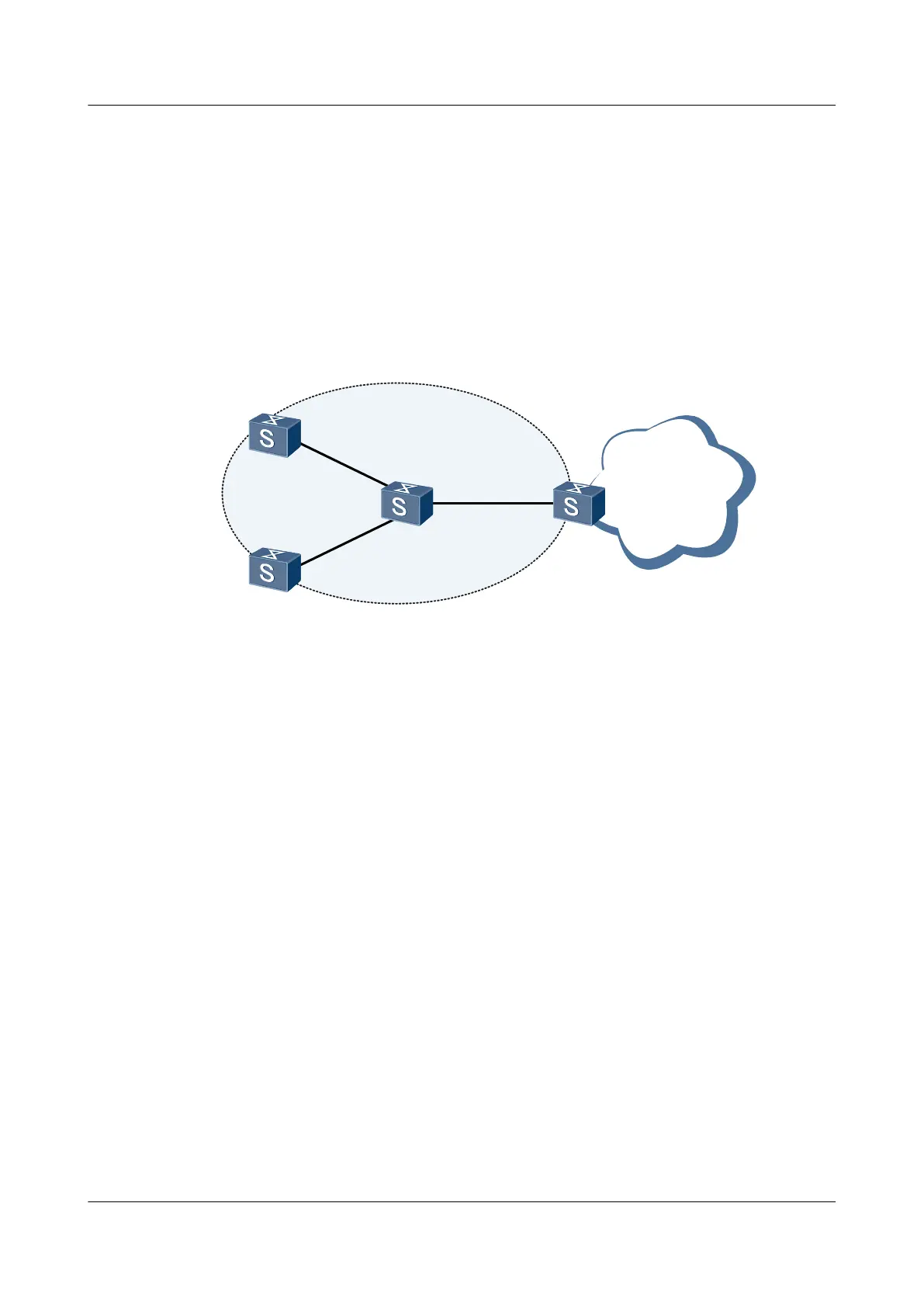
As shown in Figure 10-1, in a network that runs OSPF, Switch-A receives routes from the
Internet and provides some of these routes for Switch-B. Switch-A is required to provide
172.1.17.0/24, 172.1.18.0/24, and 172.1.19.0/24 to Switch-B. Switch-C receives only
172.1.18.0/24 and Switch-D receives all routes provided by Switch-B.
Figure 10-1 Networking diagram for filtering received and advertised routes
172.1.16.0/24
172.1.17.0/24
172.1.18.0/24
172.1.19.0/24
172.1.20.0/24
XGE0/0/1
XGE0/0/1
XGE0/0/2
XGE0/0/3
XGE0/0/1
XGE0/0/1
Switch C
OSPF
Switch D
Switch B
Switch A
Switch
Interface VLANIF Interface IP Address
SwitchA XGE 0/0/1 VLANIF 10 192.168.1.1/24
SwitchB XGE 0/0/1 VLANIF 10 192.168.1.2/24
SwitchB XGE 0/0/2 VLANIF 20 192.168.2.1/24
SwitchB XGE 0/0/3 VLANIF 30 192.168.3.1/24
SwitchC XGE 0/0/1 VLANIF 20 192.168.2.2/24
SwitchD XGE 0/0/1 VLANIF 30 192.168.3.2/24
Configuration Roadmap
The configuration roadmap is as follows:
1. Create the ID of the VLAN to which each interface belongs.
2. Assign an IP address to each VLANIF interface.
3. Configure basic OSPF functions on Switch-A, Switch-B, Switch-C, and Switch-D.
4. Configure static routes on Switch-A and import these routes into OSPF.
5. Configure the policy for advertising routes on Switch-A and check the filtering result on
Switch-B.
6. Configure the policy for receiving routes on Switch-C and check the filtering result on
Switch-C.
S6700 Series Ethernet Switches
Configuration Guide - IP Routing 10 Routing Policy Configuration
Issue 01 (2012-03-15) Huawei Proprietary and Confidential
Copyright © Huawei Technologies Co., Ltd.
617

 Loading...