KE-2050/KE-2060, KE-2050R/2055R/KE-2060R Maintenance Manual
5-18
Rev. 2.00
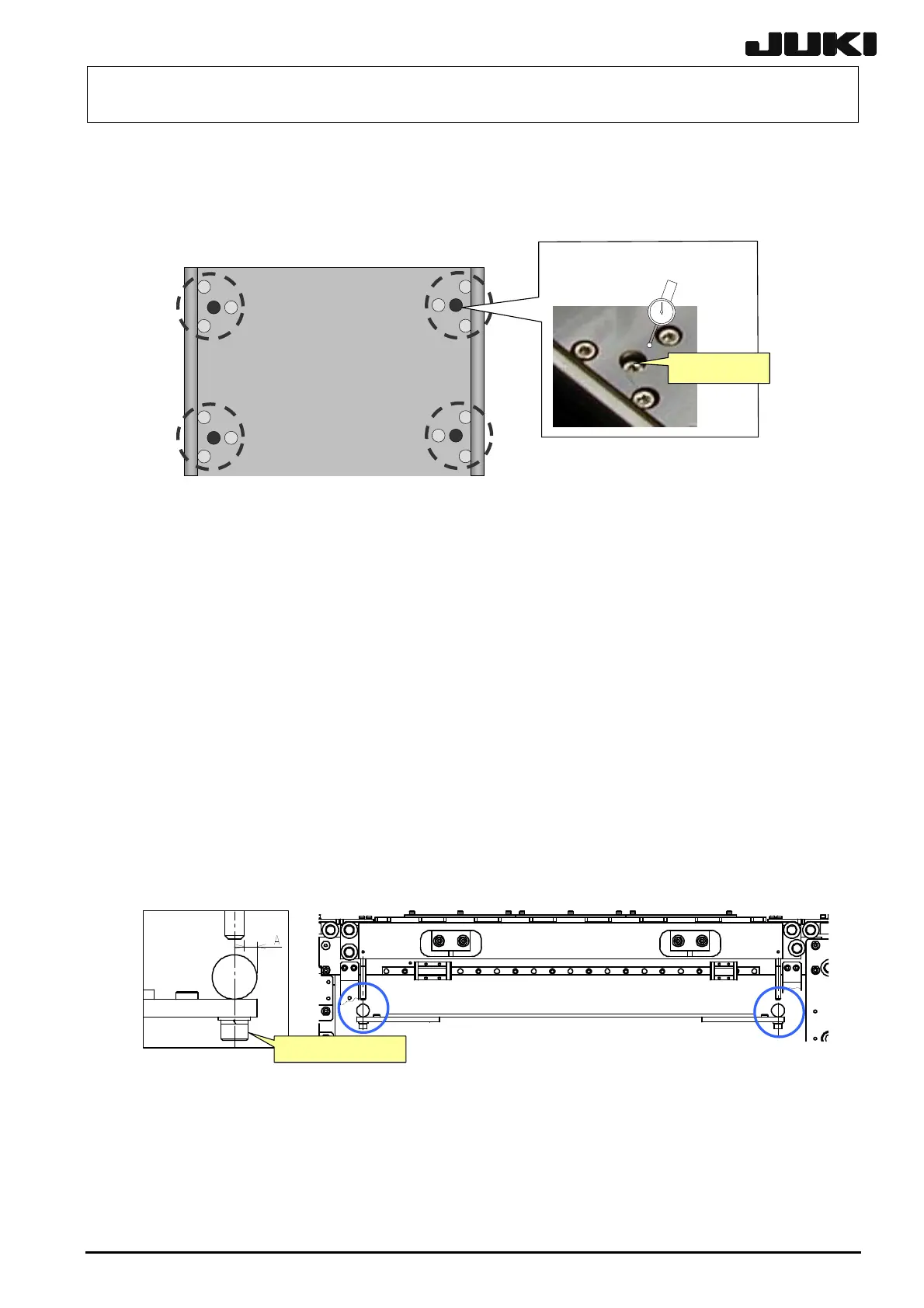
5-15-3. Placing the Support Table Surface Horizontally
To check flatness of the support table, attach a lever dial to the head's OCC camera bracket and
measure flatness near the center of each area circled in the figure below. Adjust the height of the
table so that the difference in flatness at the four positions is within 0.02 mm.
調節ねじ(中央)
Figure 5-15-3-1
<Adjustment Procedure>
(1) Select [Manual control] → [Independent control of conveyor] to move the support table to
“−27mm” position.
(2) Determine the lowest measurement point of four measurement points to the reference point.
Based on this reference point, turn the adjustment screw in the down direction (screw
tightening direction) to carry out the adjustment so that the height difference among four
measurement points is 0.02 mm or less.
☯
If all of three screws (screws around the adjustment screw) securing the ball screw are
loosened, the table may lower. To prevent this trouble, always tighten these screws
temporarily after the adjustment has been performed with the adjustment screw.
☯
After the adjustment has been completed, check that the center of the rail guide shaft is
matched with that of the side beam. (Dimension A, 4 mm
±
0.5 )
Adjustment screw
(center)
サイドビーム止めね
じ
Side beam set screw
 Loading...


