KE-2050/KE-2060, KE-2050R/2055R/KE-2060R Maintenance Manual
14-28
14-4-11. IP-X3 Board Assembly A (40001920 for KE-2050/50R),
IP-X3 Board Assembly B (40001921 for KE-2060/55R/60R)
[Functions]
These boards are image processing boards which process the image data captured by the OCC
or VCS camera such as board marks, IC marks and IC chips, and calculate the values
necessary for correcting the positions of board and parts.
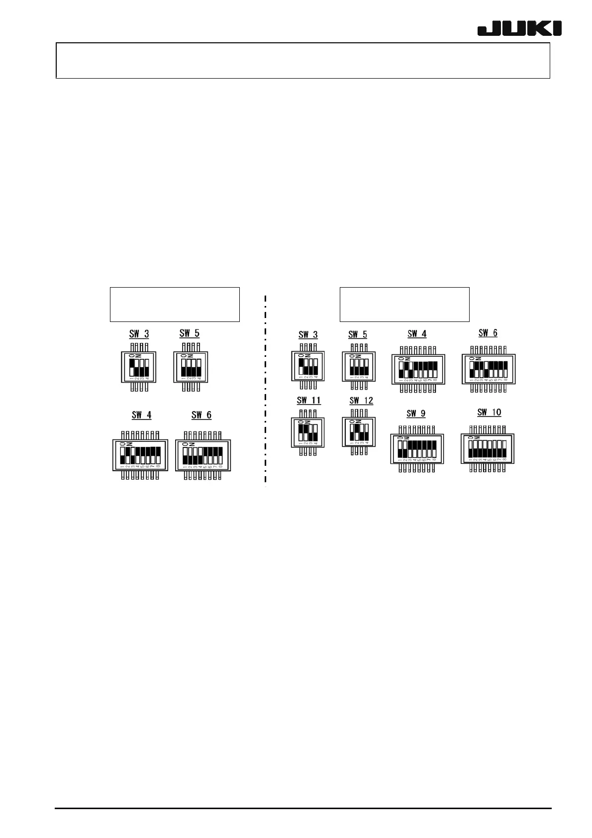
[Jumper switch settings]
The DIP switches have already been set at delivery. However, check that the DIP switches are
set as shown below before setting the board assembly in the control unit.
DIP SW settings for
IP-X3 board assembly A
DIP SW settings for
IP-X3 board assembly B
■ indicates the position of the switch.
[Front panel SW]
RESET SW: Resets this board.
ABORT SW: Sends NMI to the host CPU.
Do not operate these two switches.
[Meaning of LED]
LED 1 (Green): Lit while the CPU is running normally.
LED 2 (Red): Lights up if an error such as bus error occurs in the local bus and the CPU
enters the HALT state.
LED 3 (Red): Lights up if the system enters the FAIL state.
(If the board malfunctions, both LED 2 and LED 3 will light up.)
[Adjustment items after replacement]
After that, follow the steps below to update the FLASH memory.
c Select [Options] and [Change User Group], and then select [Service Engineer].
d Select [Maintenance] and [MS Parameter Setup].
e Select [Others], [Version-up], and [Image].
Rev. 2.00
 Loading...


