KE-2050/KE-2060, KE-2050R/2055R/KE-2060R Maintenance Manual
5-9
Rev. 2.00
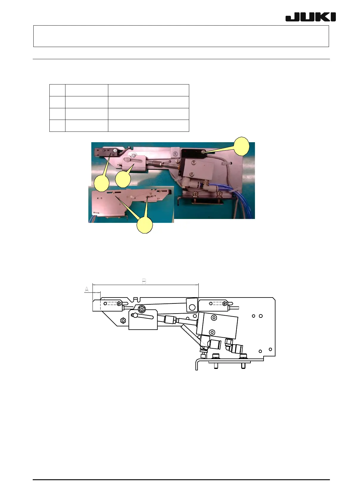
5-7. Replacing the STOP and C. OUT Sensors
(1) Remove the screws fixing the STOP and C. OUT sensors from the stopper to replace the
sensors.
40000905 STOPER_FR_ASM
40002214 STOP SENS ASM
40002235 C.OUT_SENS_ASM
SL4031291SC SCREW
Figure 5-7-1
(2) When installing new STOP and C.OUT sensors, adjust their positions as follows.
STOP sensor A = 8 mm
C.OUT sensor B = 116 mm (95 mm in the case of L size)
For your reference, the distance from STOP sensor ON to the stopper end will be 28.8 mm
when the solenoid valve is turned ON manually and a PCB is placed in the transport path.
(3) Carefully handle the air tubes and cables.
(4) Make an adjustment so that a (matte) black glass epoxy PWB placed on the transport path can
be detected. Place a (matte) black glass epoxy PWB under the sensor and rotate the sensitivity
adjustment knob of the sensor counterclockwise. Then gradually rotate it clockwise up to the
position at which the specified PWB is detected.
☯
If the black glass epoxy PWB is not available, use the darkest PWB of those to be used.
①
②
③
④
 Loading...


