KE-2050/KE-2060, KE-2050R/2055R/KE-2060R Maintenance Manual
5-13
Rev. 2.00
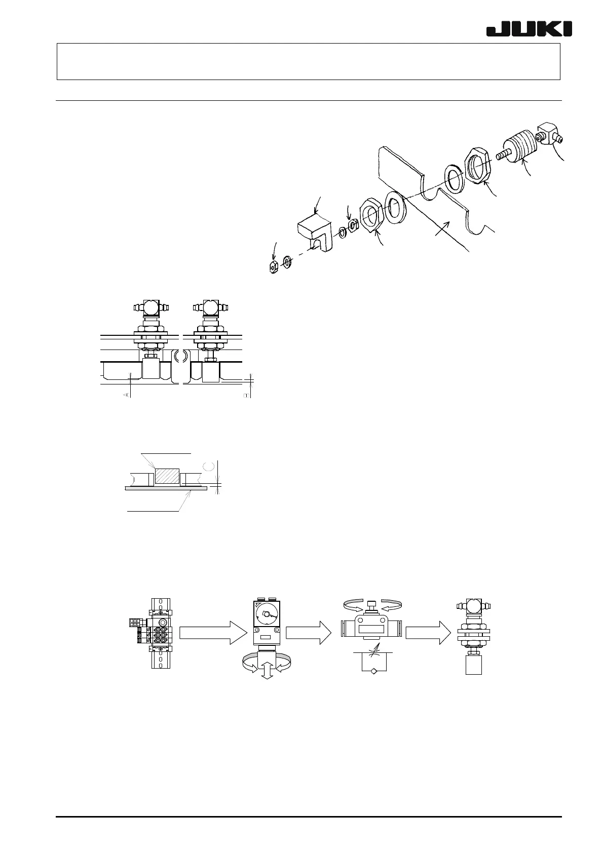
5-11. Replacing the Pusher Y Cylinder (Outer Shape Reference)
(1) Detach the par or
from the cylinder .
(2) Loosen the nut (accessory)
of the cylinder to detach
it from the part .
(3) Loosen the nut
(accessory) to detach the
pusher B from the top of
the cylinder .
(4) Reassemble the components in the reverse
order of steps (1) to (3). When installing a new
pusher Y cylinder, check and adjust as
described below.
Adjust so that the distance B is 1.5 mm ±
0.1mm when the Y pusher is ON
(extruded) and distance A is -0.5 mm ±
0.1mm when the Y pusher is OFF (not
extruded). (See Figure 5-11-2.)
djust so that the gap C between the Y
pusher and transport belt is 0.2 mm
minimum.
Figure 5-11-3
Adjust so that the pressure reducing valve is 0.5 MPa and the speed controller is opened
two rounds from the fully closed position.
Solenoid valve
Pressure reducing valve:
0.5 Mpa
Speed controller:
Opened two rounds from the
fully closed position
(Must be fixed with the lock nut.)
Y pusher
After the components have been reassembled, supply air (0.49 MPa) and check that the
pusher operates smoothly when the air is turned ON and OFF.
Figure 5-11-2
Y
ushe
Transport belt
Figure 5-11-1
 Loading...


