KE-2050/KE-2060, KE-2050R/2055R/KE-2060R Maintenance Manual
14-34
14-7. Transport Unit
14-7-1. Structure of Transport Unit
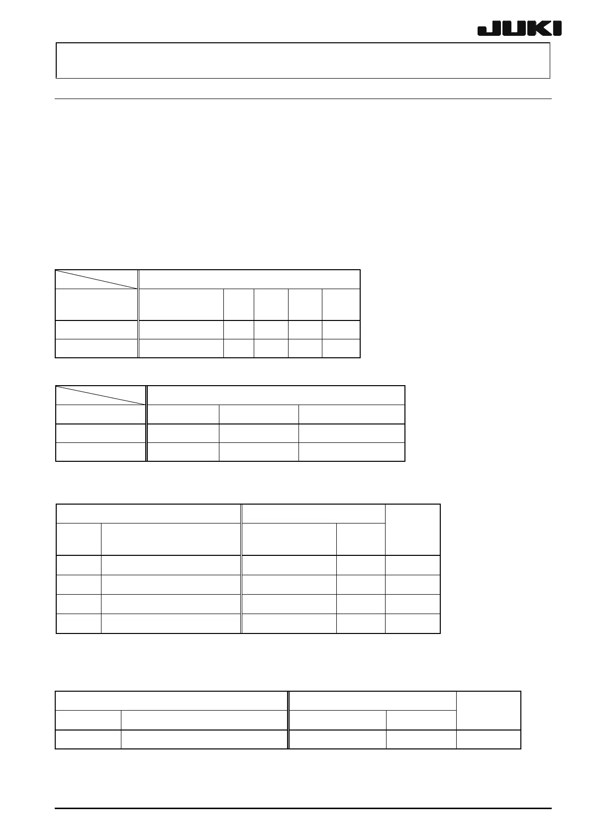
Table 14-7-1-1 shows the structure drawing of the transport unit.
The CARRY board is mounted at the center of the base frame; the transport stepping driver on the
right side of it; and the backup stepping driver on the left side of the front of the base frame.
The connection destination boards of the IN motor, OUT motor, IN sensor, OUT sensor, and WAIT
sensor in the transport unit may vary depending on the machine reference position and transport
direction as shown in Table 14-7-1-1. Connect the motors and sensors while referring to this table.
Table 14-7-1-1
Connection destination
Applicable cable
No.
Connection
destination board
FL FR RL RR
40002084 CARRY board CN2
CN38
CN38
CN2
40002083 CARRY board CN3
CN39
CN39
CN3
FL: Front reference, transport direction L→R
FR: Front reference, transport direction R→L
RL: Rear reference, transport direction L→R
RR: Rear reference, transport direction R→L
The connection with the motors is as follows.
Motor to be connected
Applicable cable No. Part No. Part name Relay connector No.
40002084 E9456729MAO OUT motor assy.
CN672
40002083 E9454729MAO IN motor assy. CN671
The cable assemblies shown in the table below are to be added or deleted in EN specification.
Connect them as shown in the table.
Applicable cable Connection destination
Part No. Part name Name of destination
Connector
No.
Add/delete
40002241
BU LOCK SENS ASM
----- CN446
Add
40002242
BU LOCK CABLE ASM CARRY sensor relay (L)
CN405L
Add
40002281
BU LOCK RLY CABLE ASM(EN) CARRY board
CN644
Add
40002340 SHORT WIRE ASM
CARRY board
CN644
Delete
The cable assemblies shown in the table below are to be added or deleted in case of COPLA
option.
Connect them as shown in the table.
Applicable cable Connection destination
Part No. Part name Name of destination Connector No.
Add/delete
40002289 COPLA I/F CABLE ASM CARRY board CN604/619 Add
Rev. 2.00
 Loading...


