KE-2050/KE-2060, KE-2050R/2055R/KE-2060R Maintenance Manual
8-3
8-2. Replacing the Standard VCS→Optional VCS Switching Cylinder
Rev. 2.00
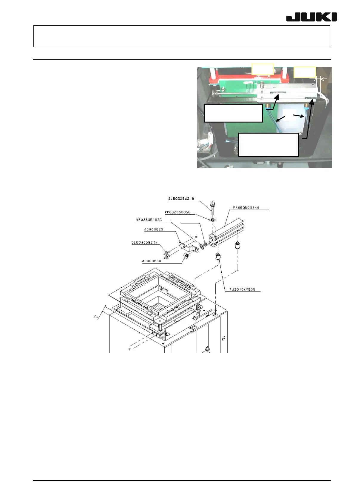
(1) Close the finger valve to shut down supply of
air to the machine.
Disconnect the air tub(2) es c and detach the
(3) ee
VCS sensor assemblies (see Figure 8-2-1).
Replace the cylinders with new ones (s
Figure 8-2-2). Assemble the components so
that there is no tendency for any load to be
exerted on the cylinders.
Figure 8-2-2
<How to adjust the air cylinder>
ptional VCS sensor) so that the distance between the left
(2) falls at the position of 7 mm when the cylinder is
(1) Assemble the VCS sensor (or the o
end surface of the air cylinder and the front end surface of the sensor is 17.5 mm (or the rear
end surface of the sensor protrudes from the right end surface of the air cylinder by 5 mm) (see
Figure 8-2-1). After assembling, check to make sure that the sensor performs detection
correctly.
Adjust the air cylinder so that the slide unit
most stretched. (See Figure 8-2-2.)
Fixing nut
ir cylinder (× 1)
17.5 mm
5 mm
40002146
VCS sensor assy.
c
40002147
Optional VCS
sensor assy.
Figure 8-2-1
Washer (
1)
VCS slider (
1)
M3 × 6 bolt (
4)
M3
25 bolt (
4)
Washer (
2)
1)
Fixing nut
ir cylinder (× 1)
Slide spacer nut (
Half union ( 2)
 Loading...


