KE-2050/KE-2060, KE-2050R/2055R/KE-2060R Maintenance Manual
2-1
DANGER
To prevent any trouble caused by accidental machine start, always
shut-down the power before starting the maintenance and
adjustment work.
[2] HEAD UNIT
2-1. Replacing and Adjusting the Head
2-1-1. MNLA Head
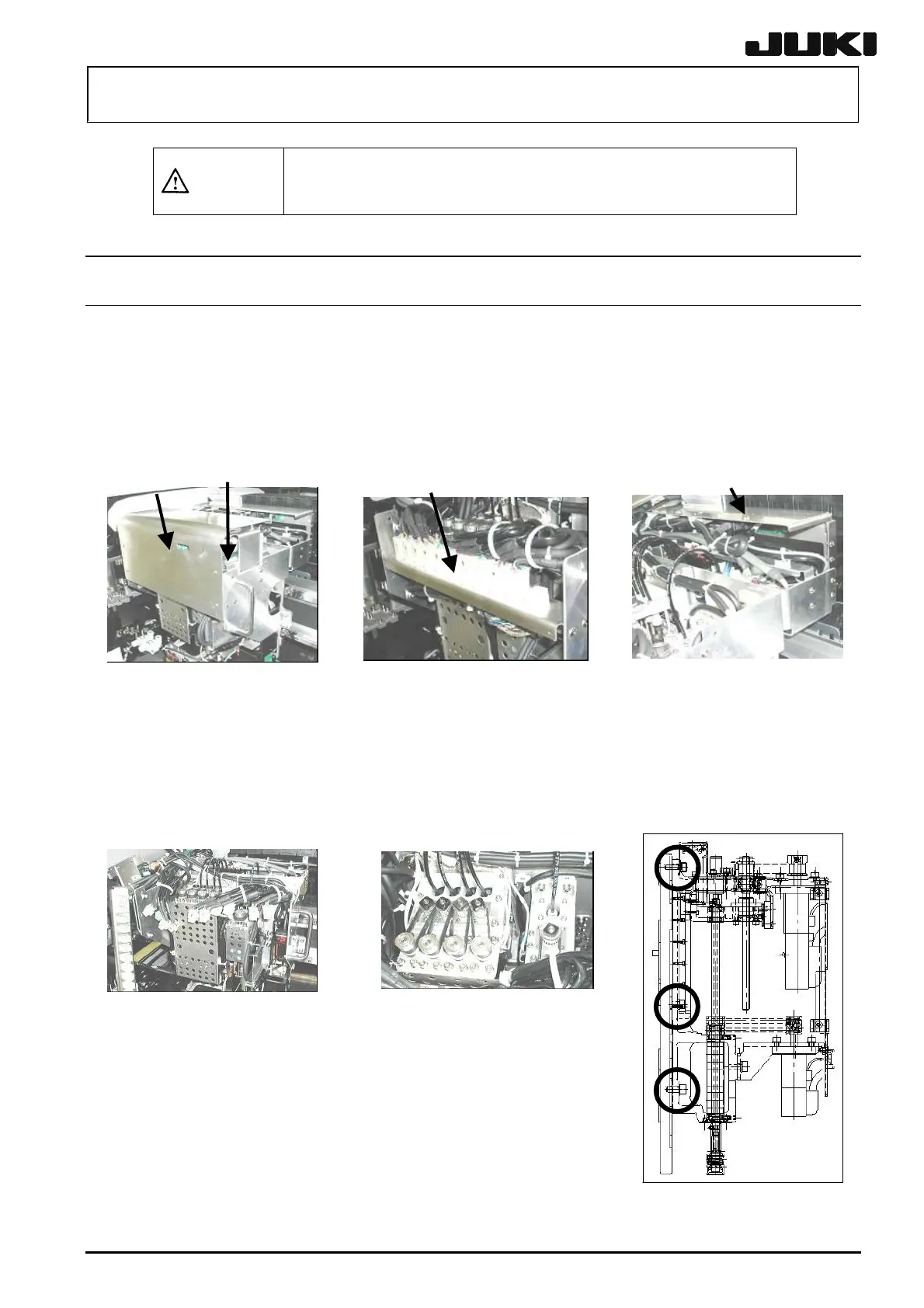
(1) Detach the head cover c. (4 mounting screws)
(2) Remove the base d of the head main board. (2 mounting screws respectively on both sides)
(3) Remove the base e of the connector. (2 mounting screws respectively on both sides)
(4) Remove the base f of the OCC relay board. (2 mounting screws respectively on both sides)
Figure 2-1-1 Figure 2-1-2 Figure 2-1-3
c
d
f
e
(5) Keep all the d, e and f on the left side of the head. (See Figure 2-1-4.)
(6) Remove the air tube from the half union. (See Figure 2-1-5.)
(7) Disconnect the connector of the Z sensor cable from the head sensor board. Cut the tie-up
band binding the cable at midpoint. (See Figure 2-1-5.)
(8) While keeping the head by hand so that it does not fall down, remove the SEMS cap bolts g (6
pcs.). (See Figure 2-1-6.)
Figure 2-1-4 Figure 2-1-5
(9) Pull out the two parallel pins at the top and bottom of the
head from the head plate. Then raise the head to detach it so
that it is not in contact with other components.
(10) Reassemble the components in the reverse order of
disassembly.
Apply Loctite 242 to the head mounting screws g (6
pcs.) and tighten them with a tightening torque of 7.0
N・m.
Figure 2-1-6
Rev. 2.00
 Loading...


