1-S35
BX24, RCK54(P)-23BX, RCK60B-23BX, LA240, BT601, WSM
ENGINE
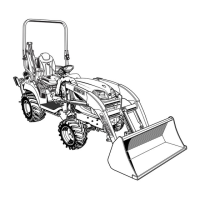
Fuel Camshaft
1. Remove the retaining plate (1).
2. Remove the fork lever holder mounting screws (8), then draw out
the injection pump gear (3) and fuel camshaft (2) with the
governor fork assembly.
(When reassembling)
• Hook the governor spring (7) to the fork lever 2 (6) as shown in
the figure before installing the fork lever assembly to the
crankcase.
W10178820
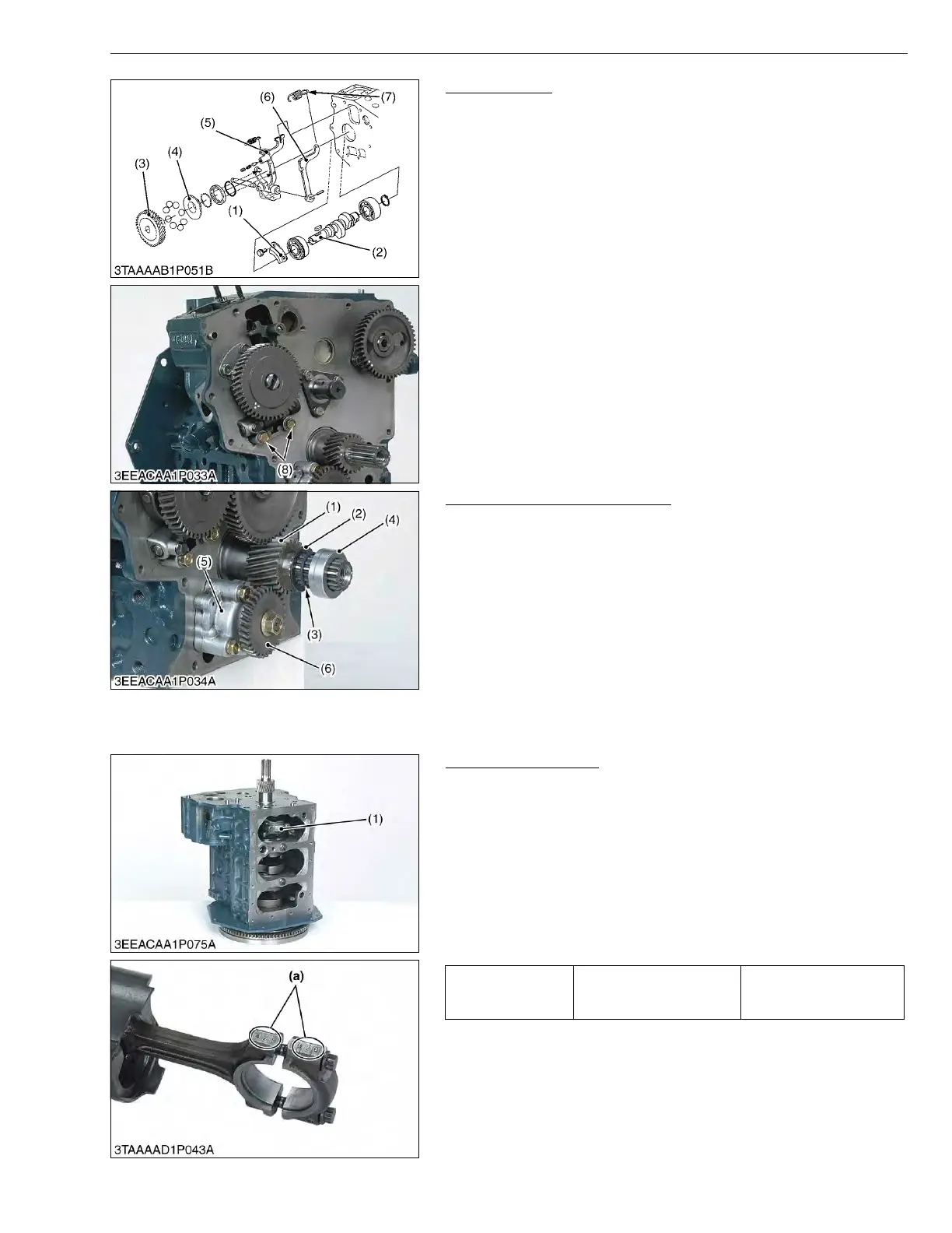
Oil Pump and Crankshaft Gear
1. Remove the oil pump gear (6).
2. Remove the oil pump (5).
3. Remove the collar (4), O-ring (3) and crankshaft oil slinger (2).
4. Remove the crankshaft gear (1) with a puller.
(When reassembling)
• Install the collar (4) after aligning the marks on the gears. (See
page 1-S34 “Idle Gear”.)
W10180290
(5) Piston and Connecting Rod
Connecting Rod Cap
1. Remove the connecting rod caps (1) using a bihexagonal 8 mm
socket.
(When reassembling)
• Align the marks (a) with each other. (Face the marks toward the
injection pump.)
• Apply engine oil to the connecting rod screws and lightly screw it
in by hand, then tighten it to the specified torque.
If the connecting rod screw won’t be screwed in smoothly, clean
the threads.
If the connecting rod screw is still hard to screw in, replace it.
W10275480
(1) Retaining Plate
(2) Fuel Camshaft
(3) Injection Pump Gear
(4) Governor Sleeve
(5) Fork Lever 1
(6) Fork Lever 2
(7) Governor Spring
(8) Fork Lever Holder Mounting Screw
(1) Crankshaft Gear
(2) Crankshaft Oil Slinger
(3) O-ring
(4) Crankshaft Collar
(5) Oil Pump
(6) Oil Pump Gear
Tightening torque Connecting rod screw
26.5 to 30.4 N·m
2.7 to 3.1 kgf·m
19.5 to 22.4 ft-lbs
(1) Connecting Rod Cap (a) Mark

 Loading...