5-M3
BX24, RCK54(P)-23BX, RCK60B-23BX, LA240, BT601, WSM
HYDRAULIC SYSTEM
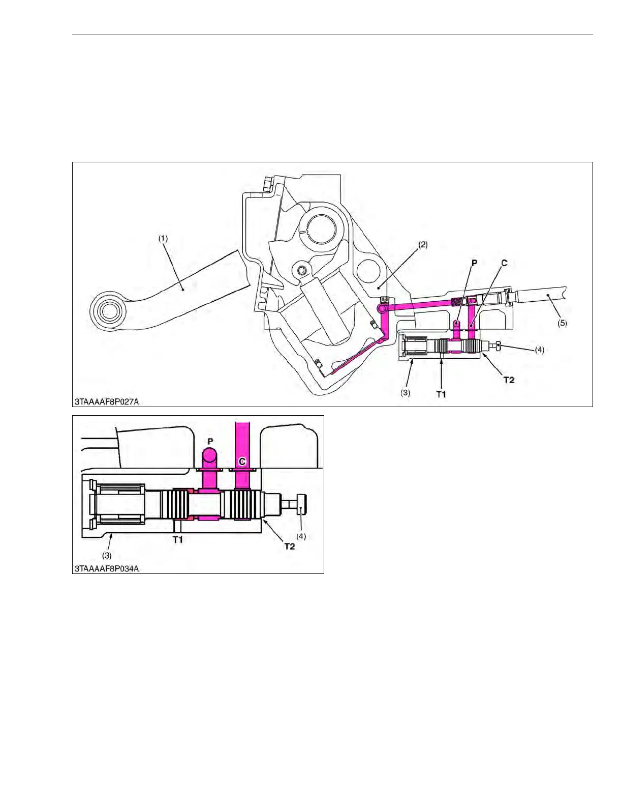
3. CONTROL VALVE
This position control valve is located under the hydraulic cylinder.
This control valve is mechanically connected to the position control lever.
Since the feedback rod is not equipped to the lift arm, the neutral position adjustment is adjusted by controlling the
position control lever.
The control valve controls the oil flow forced from the hydraulic pump and the oil returned back from the hydraulic
cylinder.
Neutral
When stopping the position control lever, the spool is
stopped.
The spool closes the oil flow from passage between
P port and C port.
Since the oil in the hydraulic cylinder is not drained to
T2 port, “Neutral” position is kept.
W1015913
(1) Lift Arm
(2) Hydraulic Cylinder
(3) Control Valve
(4) Spool
(5) Lowering Adjusting Shaft
P : Pump Port
C : Cylinder Port
T1 :Tank Port
T2 :Tank Port

 Loading...