8-S10
BX24, RCK54(P)-23BX, RCK60B-23BX, LA240, BT601, WSM
FRONT LOADER
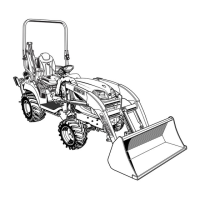
Control Valve
1. Remove the loader frame (6).
2. Disconnect the cruise control rod (2).
3. Disconnect the frame loader control rods (3).
4. Remove the brake spring.
5. Remove the arms (4) from spool end.
6. Remove the stay bolt (5).
7. Remove the valve stay (7).
8. Disconnect the pipes (1).
9. Remove the control valve (8) with pipes.
(When reassembling)
• After reassembling a valve, check for oil leakage by starting up
an engine.
• When starting up engine, watch out for the rotating propeller
shaft (9).
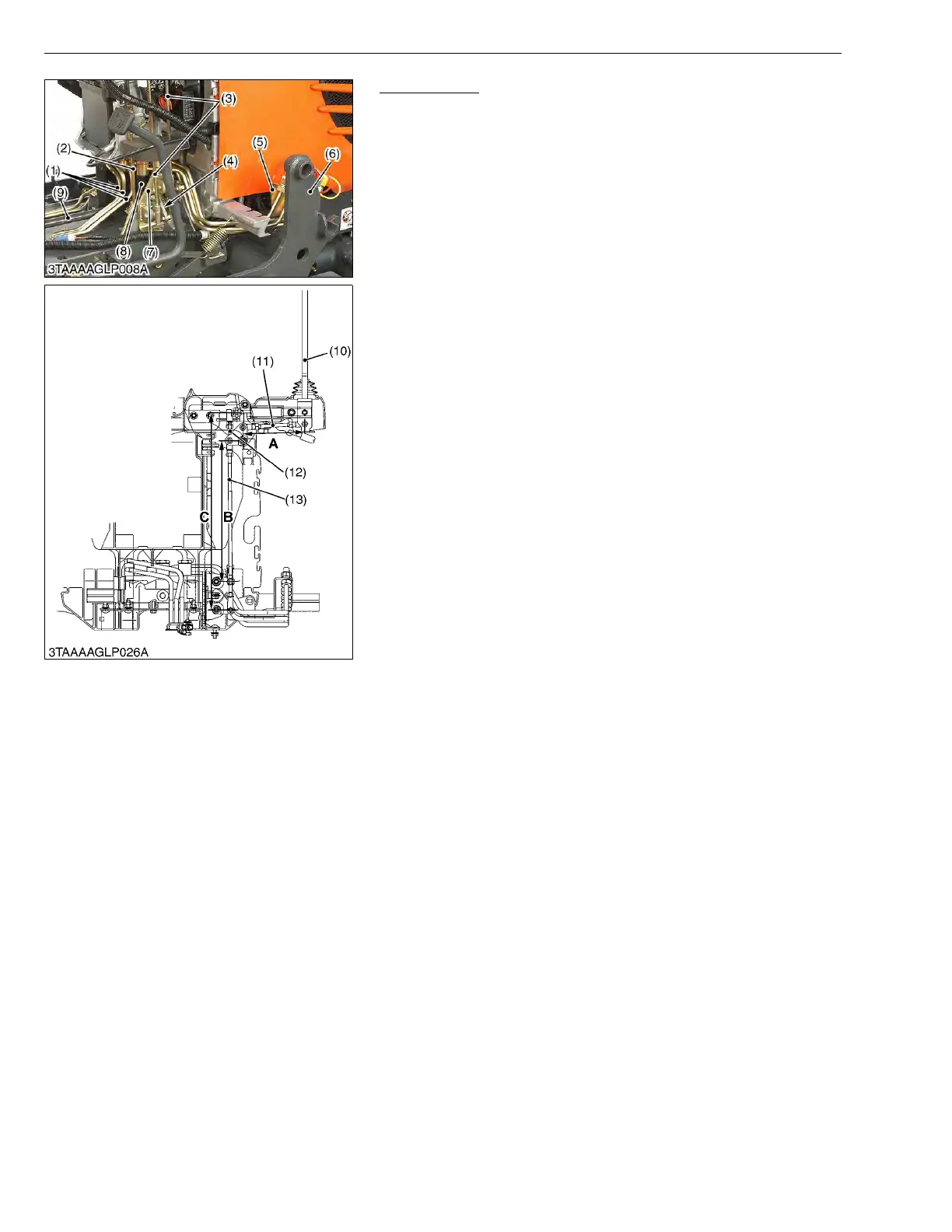
(Reference)
• When adjusting the length of rods, make the lever come to the
neutral position.
A : 145 mm (5.71 in.)
B : 315 mm (12.46 in.)
C : 448 mm (17.64 in.)
W1013522
(1) Pipe
(2) Cruise Control Rod
(3) Front Loader Control Rod
(4) Arm
(5) Stay
(6) Loader Frame
(7) Valve Stay
(8) Control Valve
(9) Propeller Shaft
(10) Front Loader Control Lever
(11) Rod 1
(12) Rod 2
(13) Rod 3

 Loading...